Battery Monitoring System
a battery monitoring and battery technology, applied in battery/fuel cell control arrangement, instruments, electric devices, etc., can solve problems such as erroneous diagnosis and wrong decision, and achieve the effect of reducing errors during transmission and reception operation and extending data length
- Summary
- Abstract
- Description
- Claims
- Application Information
AI Technical Summary
Benefits of technology
Problems solved by technology
Method used
Image
Examples
first embodiment
The First Embodiment
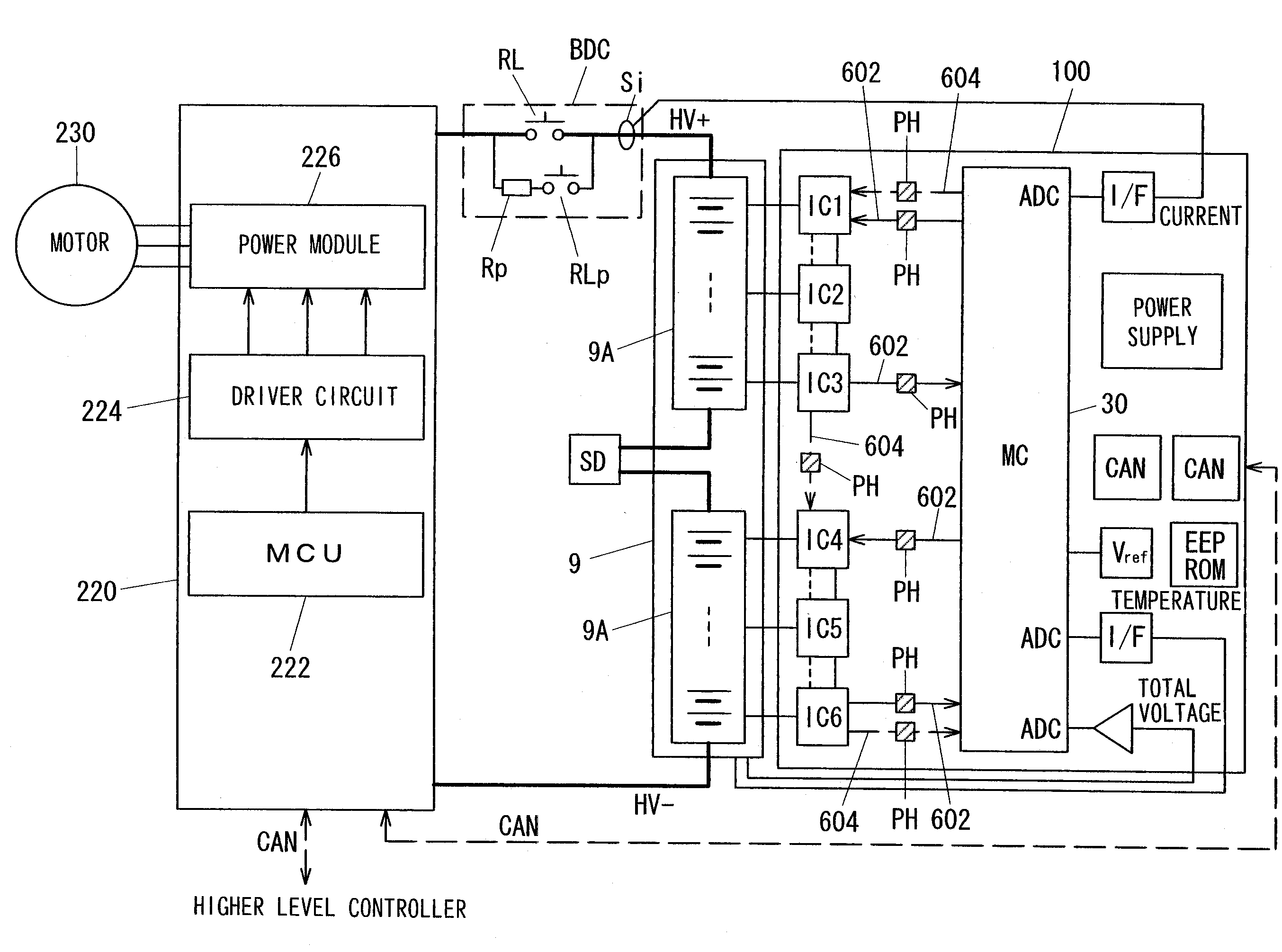
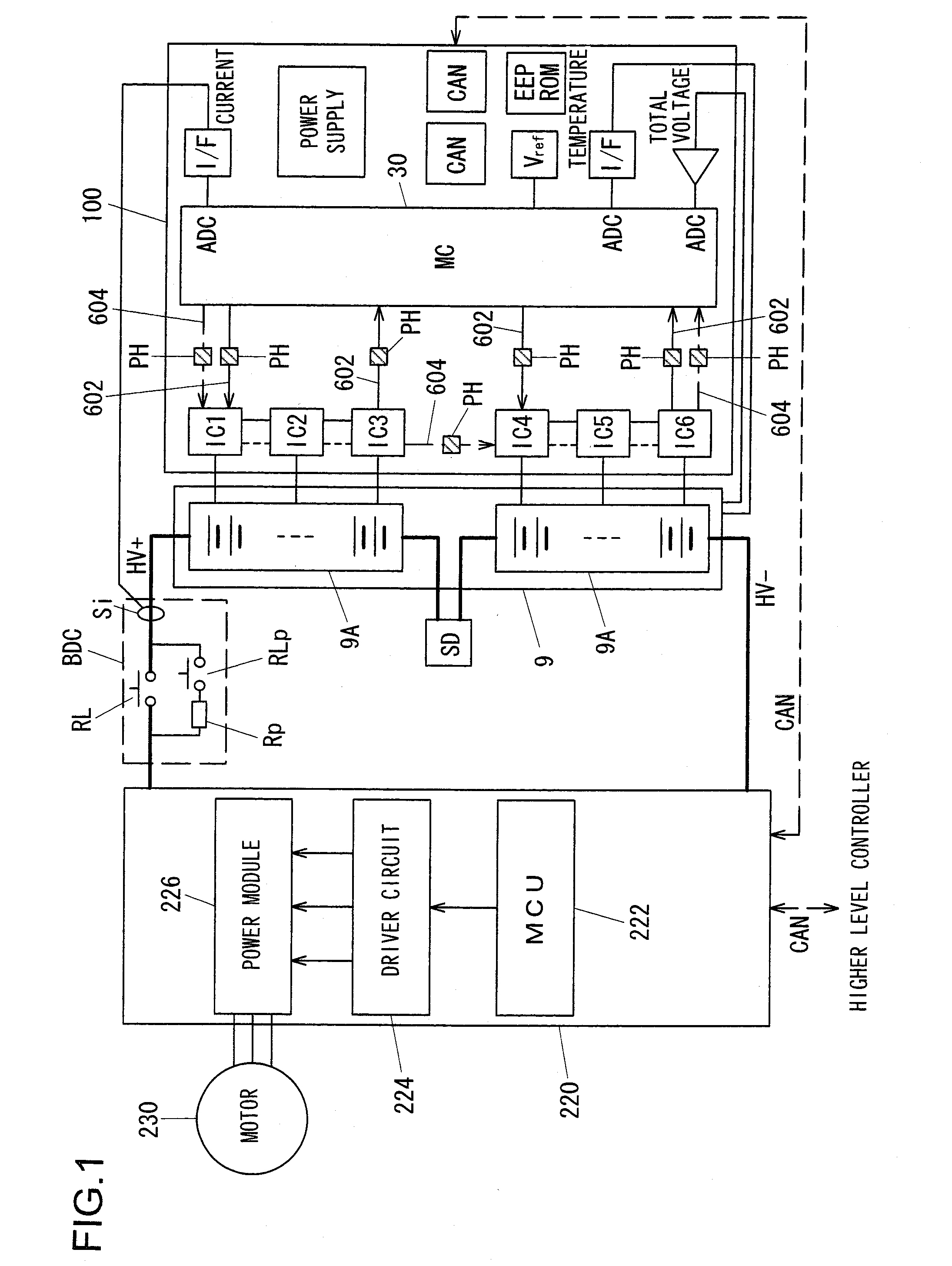
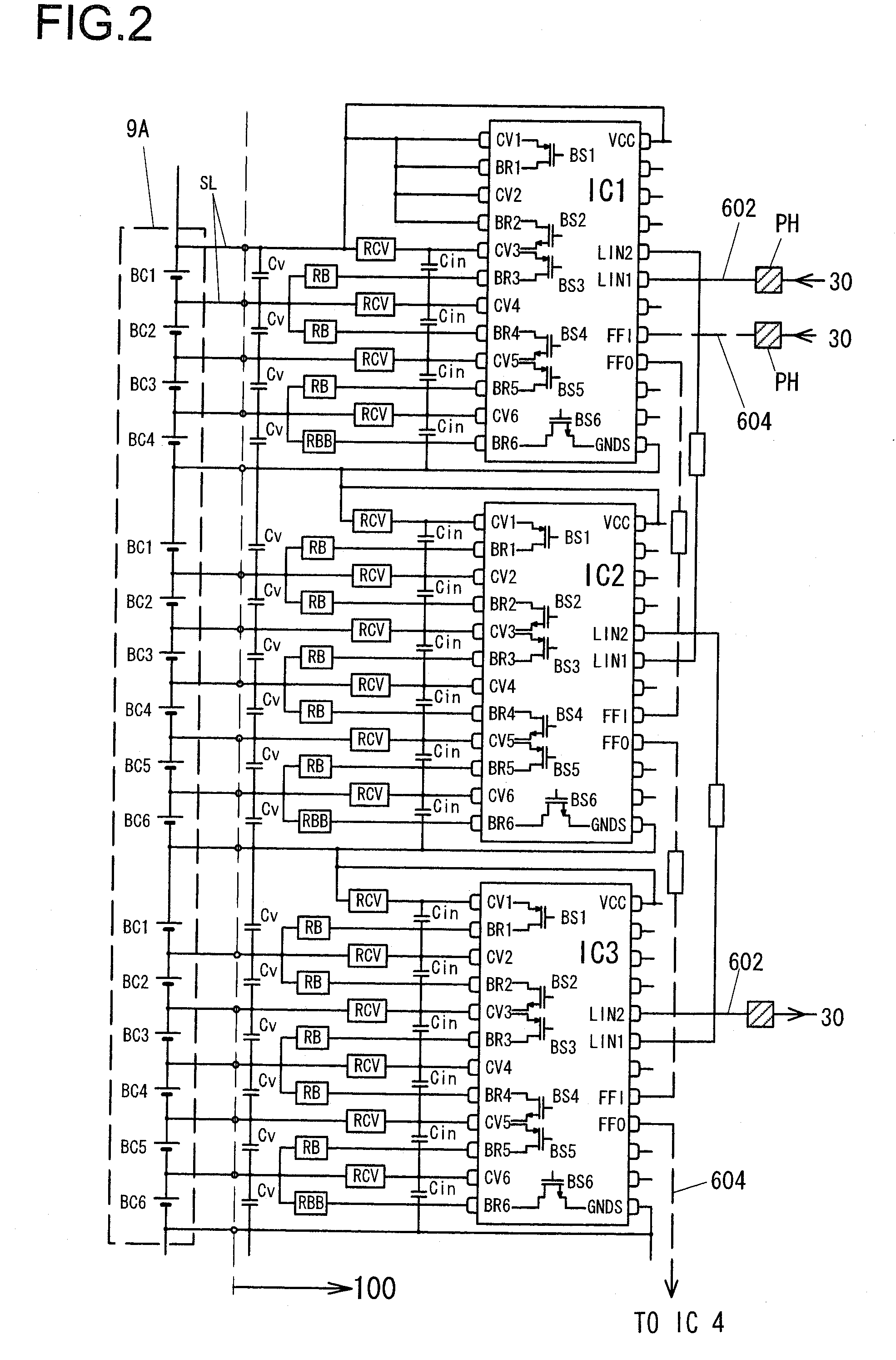
[0130]As described above, when performing cell voltage measurement, from among the terminals CV1 through CV6 and the GNDS terminal, a pair of terminals that are connected to both of the electrodes of the battery cell that is to be the subject of measurement are selected by the multiplexer 120 shown in FIG. 3. A selection signal for this terminal selection is generated by a digital region within IC2 (the IC control circuit 123 of FIG. 3), and is inputted to the multiplexer 120. However, if a malfunction occurs in the multiplexer 120, then sometimes it may happen that different terminals from those in the command containing the selection signal are selected. In this type of case as well, in the prior art, from the cell voltage transmitted to the side of the microcomputer 30, it was not possible to determine whether or not the cell voltage that was measured had been correctly selected. Accordingly, as explained below, in this first embodiment it is arranged for it t...
second embodiment
The Second Embodiment
[0166]In the second embodiment explained below, it is arranged to provide a function of diagnosing whether or not the battery state detection circuit is operating normally, in other words a function of diagnosing whether or not selection by the multiplexer is being performed normally, and also newly to add a function of diagnosing whether or not an excessive charge detection circuit (an excessive charge detection system) that detects excessive charge is operating normally.
[0167]Multiplexer Selection Diagnosis
[0168]FIG. 13 is a figure for explanation of this second embodiment, and shows blocks internal to the integrated circuits (IC1 through IC6), in a similar way to the case in FIG. 5. To IC1 shown in FIG. 13, in addition to the structure shown in FIG. 5, there are further provided multiplexers MUX1 through MUX5, resistors RPU, R1 through R4, and RPD, and a switch SW. It should be understood that only structures within the structure shown in FIG. 5 that are nece...
third embodiment
The Third Embodiment
[0205]FIG. 18 is a figure for explanation of a third embodiment, and is a block diagram similar to FIG. 13. In the structure shown in FIG. 18, bypass switches SW0 through SW4 are added to the structure of the second embodiment shown in FIG. 13. By doing this, along with performing diagnosis of the multiplexers HVMUX1 and HVMUX2 in a similar manner to the second embodiment, it is also possible to perform separate diagnosis of the excessive charge detection circuit. Moreover, in this embodiment, it is possible for the multiplexers HVMUX1 and HVMUX2 to be changed over so as to select the same input terminals. In this case, they could be changed over with the signals STG1 and STG2, or it would also be acceptable for them to be changed over by command from the microcomputer 30. In the example shown in FIG. 18, the resistor RPD and the multiplexer MUX5 of FIG. 13 are omitted.
[0206]When performing diagnosis of the multiplexers HVMUX1 and HVMUX2, all of the bypass switch...
PUM
 Abstract
Description
Claims
Application Information
 - R&D
- Intellectual Property
- Life Sciences
- Materials
- Tech Scout
- Unparalleled Data Quality
- Higher Quality Content
- 60% Fewer Hallucinations
Browse by: Latest US Patents, China's latest patents, Technical Efficacy Thesaurus, Application Domain, Technology Topic, Popular Technical Reports.
© 2025 PatSnap. All rights reserved.Legal|Privacy policy|Modern Slavery Act Transparency Statement|Sitemap|About US| Contact US: help@patsnap.com


