Entirely integrated EMI filter based on a flexible multi-layer strip material

a multi-layer strip, fully integrated technology, applied in the direction of transformer/inductance details, variable inductance, inductance, etc., can solve the problems of inefficient space utilization, too many discrete components, and traditional emi filters, so as to reduce the impact of volume and distribution constant, reduce the size and volume of the emi filter, and reduce the insertion loss

Active Publication Date: 2010-09-30
ZHEJIANG UNIV +1
View PDF13 Cites 5 Cited by
  • Summary
  • Abstract
  • Description
  • Claims
  • Application Information

AI Technical Summary

Benefits of technology

[0019]Advantages of embodiments of the present invention include enabling all passive components of the EMI filter to be integrated in one core, so that in its differential mode, insertion loss can be sig...

Problems solved by technology

Traditional EMI filters have disadvantages including too many discrete components and inefficient usage ...

Method used


Image

  • Entirely integrated EMI filter based on a flexible multi-layer strip material
  • Entirely integrated EMI filter based on a flexible multi-layer strip material
  • Entirely integrated EMI filter based on a flexible multi-layer strip material

Examples


embodiment 1

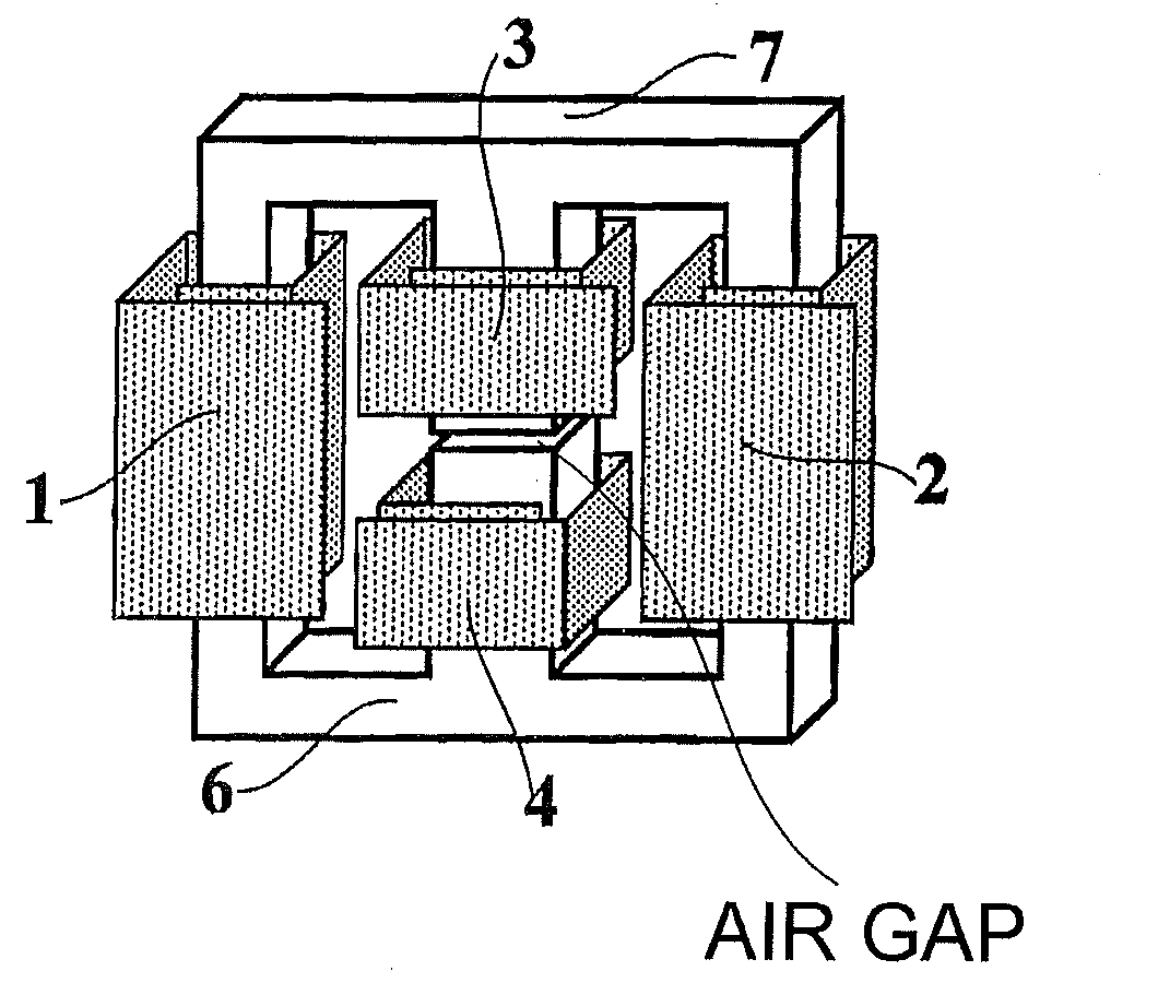
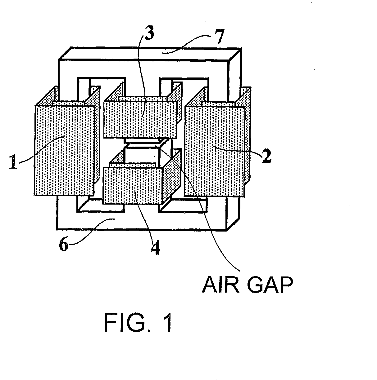
[0034]Referring to FIG. 1, an EMI filter based on a flexible multi-layer strip material according to an embodiment of the invention is shown. An EE core or EI core (6, 7) forms a closed magnetic circuit. The middle pillar has an air gap. The two windings on the side pillars are formed by winding layers, for example, four layers, of strip material, and are wound in the same winding direction with the number of turns in each winding being identical. Similarly, the two windings on the middle pillar are formed by winding layers, for example, four layers, of strip material, and are respectively wound in directions opposite to each other, with the numbers of the turns in the windings being the same.

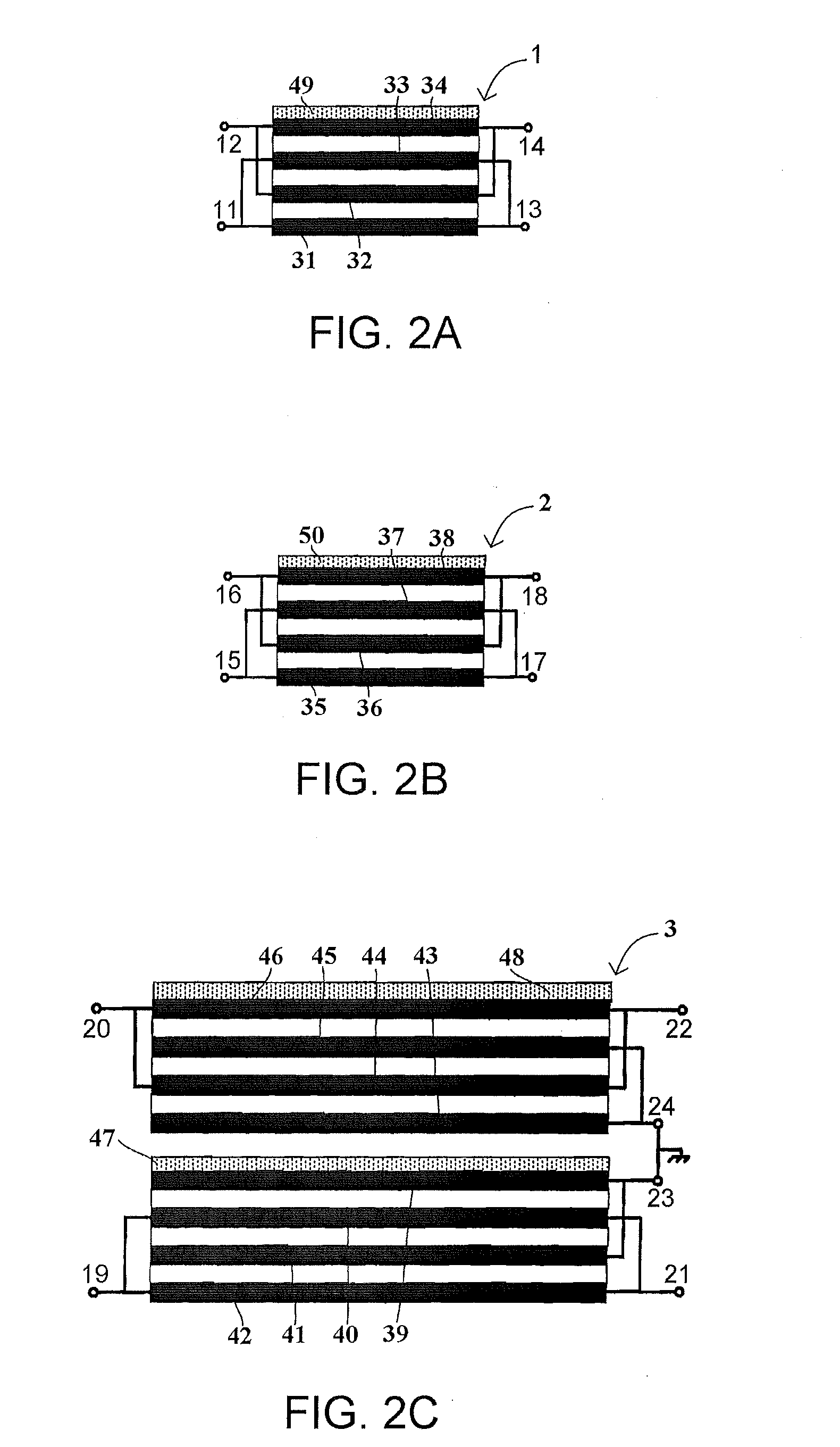
[0035]The two windings (the first winding 1 and the second winding 2) on the side pillars are formed by winding 2N or more layers (N is a positive integer; in this embodiment, four (N=2) layers of copper foils as illustrated in FIGS. 2A and 2B) of flexible multi-layer strip material and are wou...

embodiment 2

[0049]Referring to FIG. 4, an EMI filter based on a flexible multi-layer strip material is shown. An EE core or EI core (6, 7) forms a closed magnetic circuit. The middle pillar has an air gap. The two windings on the side pillars are formed by winding layers, for example, four layers, of strip material, and are wound in the same winding direction, with the numbers of the turns in the windings being identical. Similarly, the windings on the middle pillar are formed by winding layers, for example, six layers, of strip material.

[0050]In more detail, a fifth winding 5 on the middle pillar is formed by winding 3K or more copper foil layers (K is a positive integer) of flexible multi-layer strip material around the middle pillar, and in this embodiment, six layers (K=2) of flexible multi-layer strip material are wound, as illustrated in FIG. 5. The fifth winding 5 is wound in the same winding direction as the first winding 1 and the second winding 2.

[0051]Referring to FIGS. 2A and 2B, 4 ...


PUM


Abstract

An entirely integrated EMI filter is based on a flexible multi-layer strip material. An EE or EI core comprises two side pillars and one middle pillar and forms a closed magnetic circuit. The middle pillar has an air gap. A first winding and a second winding respectively are wound around the two side pillars in a same winding direction. The middle pillar is wound with a third winding and a fourth winding, or with only a fifth winding. Passive components (e.g., all passive components) of the EMI filter are integrated into one core so that in its differential mode, insertion loss is significantly reduced, the size and volume are reduced, and the distribution constant of the EMI filter has less impact on the filter's performance.

Description

CROSS-REFERENCE TO RELATED APPLICATIONS[0001]This application claims priority under 35 U.S.C. §119 from Chinese Patent Application No. 200910097051.X, filed Mar. 30, 2009, the entirety of which is incorporated herein by reference.BACKGROUND[0002]1. Field of the Invention[0003]Embodiments of the present invention relate to an electronic device, and in particular to an entirely integrated EMI filter based on a flexible multi-layer strip material.[0004]2. Related Art[0005]Modularization, miniaturization and high density of power are a trend in electric and electronic devices. On one hand, it is desired to reduce the size of each component in an electric and electronic device. And on the other hand, a higher and higher performance is required from EMI filters due to serious electromagnetic interference (EMI). Traditional EMI filters have disadvantages including too many discrete components and inefficient usage of space. In addition, the performance of traditional EMI filters is easily ...

Claims


Application Information

Patent Timeline
IPC IPC(8): H01F27/28
CPCH01F27/2847H01F27/323H03H2001/0085H03H7/0115H03H7/09H01F37/00
Inventor XU, DEHONGWEN, ZHIWEIWU, XIAOFENGOKUMA, YASUHIROMINO, KAZUAKI
Owner ZHEJIANG UNIV
Why Eureka
Try Eureka