Data Slicer Threshold Adjustment for Disparity Controlled Signals

a technology of disparity control and data slicer, applied in the field of digital communication, can solve the problem achieve the effect of increasing the bit error rate (ber) of the link, reducing the ber, and extending the reach of the link

Active Publication Date: 2010-09-30
MACOM CONNECTIVITY SOLUTIONS LLC
View PDF7 Cites 7 Cited by
  • Summary
  • Abstract
  • Description
  • Claims
  • Application Information

AI Technical Summary

Benefits of technology

[0014]Disclosed herein is a means to optimize the slicer threshold level in the Data Recovery circuit of a Disparity Controlled signal, such as 8B10B encoded Ethernet or FibreChannel. Electrical and optical links that are 8B10B encoded use disparity to DC balance the signal. When interference is added to the channel, a DC offset can be introduced that causes the data slicer to slice at a less optimal level, which results in an increased Bit Error Rate (BER) for the link. By controlling the data slicer threshold with a control system that monitors disparity, the threshold can be optimized for individual links during operation, reducing BER and / or extending the reach of the link.

Problems solved by technology

When interference is added to the channel, a DC offset can be introduced that causes the data slicer to slice at a less optimal level, which results in an increased Bit Error Rate (BER) for the link.

Method used


Image

  • Data Slicer Threshold Adjustment for Disparity Controlled Signals
  • Data Slicer Threshold Adjustment for Disparity Controlled Signals
  • Data Slicer Threshold Adjustment for Disparity Controlled Signals

Examples


Embodiment Construction

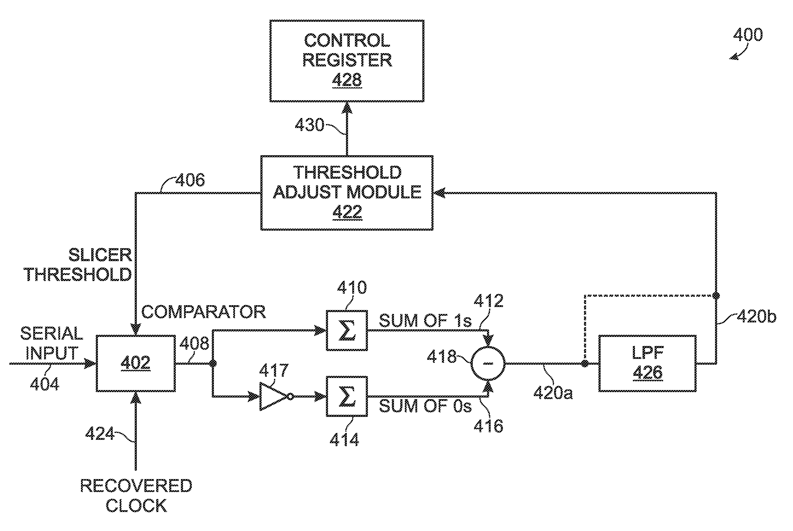
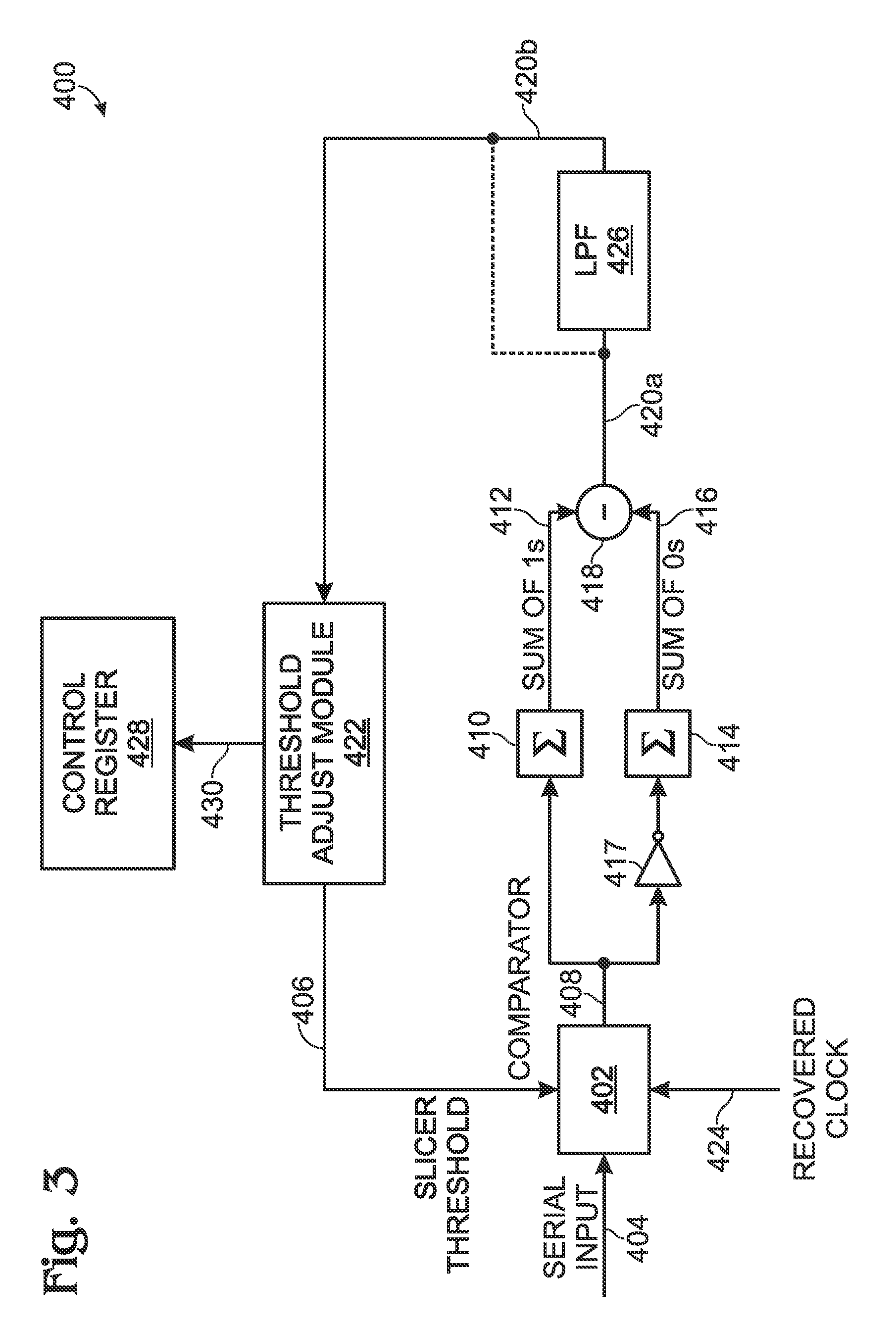
[0021]FIG. 3 is a schematic block diagram of a communications receiver with a disparity measurement system for controlling the adjustment of a data slicer threshold. The system 400 comprises a comparator 402 having an input on line 404 for receiving a serial stream of pseudorandom digital data signals having an average DC value, and an input on line 406 to accept a slicer threshold value. The comparator 400 has an output on line 408 to supply data signal “1” and “0” values, in response to comparing data signal amplitudes to the slicer threshold value. A first summing circuit 410 has an input connected to the comparator output on line 408, and an output on line 412 to supply a first sum of determined “1” values. A second summing circuit 414 has an input connected, to the comparator output on line 403, and an output on line 416 to supply a second, sum of determined “0” values. As shown, the first and second summing circuits are identical, but an inverter 417 has been interposed betwee...


PUM


Abstract

A system and method are provided for using disparity measurements to control the adjustment of a data slicer threshold. The method receives a serial stream of pseudorandom digital data signals having an average DC value, and compares data signal amplitudes to a slicer threshold value. In response to the slicer threshold value comparison, data signal “1” and “0” values are determined. A first sum of determined “1” values is created, and a second sum of determined “0” values is created. The slicer threshold value is adjusted in response to the comparison of the first and second sums. More explicitly, the slicer threshold value is adjusted to make “1” values more likely in response to the second sum being larger than the first sum. Alternately, the slicer threshold value is adjusted to make “0 ” values more likely in response to the second sum being smaller than the first sum.

Description

BACKGROUND OF THE INVENTION[0001]1. Field of the Invention[0002]This invention generally relates to digital communications and, more particularly, to a system and method for adjusting a data slicer threshold in disparity controlled signals.[0003]2. Description of the Related Art[0004]FIG. 1 is a diagram illustrating a signal recovered from a binary symmetric, non-dispersive channel in the presence of symmetric noise (prior art). Conventionally, the signal is filtered with a transfer function matched to the signaling waveform (in this case a one unit step) and thresholded at the voltage level most likely to yield the transmitted bit. To recover the transmitted information, a hard decision must he made as to the value of the received bit.[0005]As a function of the filtering process, and sometimes as a result of the transmission process, pulse spreading occurs. That is, the energy associated with a bit spreads to neighboring bits. For small degrees of spreading these effects of this ca...

Claims


Application Information

Patent Timeline
Patent Type & Authority Applications(United States)
IPC IPC(8): H04L25/06
CPCH04L25/063
Inventor CAMPEAU, SEAN
Owner MACOM CONNECTIVITY SOLUTIONS LLC
Why Eureka
Try Eureka