Assembly For Providing A Downflow Return Air Supply

a technology of return air supply and assembly, which is applied in the direction of casings/cabinets/drawers, heating types, casings/cabinets/drawers details of electric appliances, etc., can solve the problems of limiting the number of racks that can be fit into a data center, the depth of the racks, and the substantial heat generated by electrical equipment, so as to reduce the power consumption of the cooling system and increase the performance

Inactive Publication Date: 2010-09-30
WRIGHT LINE
View PDF22 Cites 82 Cited by
  • Summary
  • Abstract
  • Description
  • Claims
  • Application Information

AI Technical Summary

Benefits of technology

[0042]It is a further object of this invention to provide a rack cooling system that maintains the depth of the rack to a minimum, thus maximizing data center rack capacity.
[0075]In an additional preferred embodiment, the invention provides a method of cooling heat-generating components housed in cabinets in a data center, the method comprising providing cool air to a first region between two rows of cabinets, including a first row and a second row that is substantially parallel to the first row, with a front face of at least one of the cabinets in the first row facing towards a front face of at least one of the cabinets in the second row; inhibiting the cool air from exiting the first region through the location between a first cabinet of the first row and a first cabinet of the second row; inhibiting the cool air from exiting the first region through the location between a last cabinet of the first row and a last cabinet of the second row; exhausting warm air from the heat-generating equipment through a chimney in communication with at least one of the cabinets to a second region above the first and second row; and inhibiting the warm air from entering the first region.

Problems solved by technology

The electronic equipment generates substantial heat that must be dissipated.
However, such thickened panels increase the depth of the racks, which inherently limits the number of racks that can be fit into a data center.
As with individual equipment racks, there are heat dissipation and energy consumption issues associate with data centers.
The increasing demand, and strain, placed upon electrical grids across the United States by data centers of all sizes is a material contributor to this issue.
There has been little incentive, however, for data center managers to optimize the energy efficiency of their data center.
In addition, the industry has not set any proper benchmarks for attainable energy efficiency targets, which further complicates the situation.
Data center managers are primarily concerned about capital costs related to their data center's capacity and reliability.
(1) An open air system that delivers cold air at approximately 55 degrees Fahrenheit (approximately 13 degrees Celsius) via overhead ducting, flooded room supply air, or a raised floor plenum;
(2) Perforated tiles (in a raised floor environment) that are used to channel the cold air from beneath the raised floor plenum into the data center;
(3) Computer racks, server enclosures and free-standing equipment orientated 180 degrees from alternate rows to create hot and cold aisles, which is an accepted best practice. Historically, however, information technology (IT) architecture has been the driving force in deciding the location of the racks and other equipment, leading to a disorganized and inefficient approach to air distribution;
(4) A minimum separation of 4 feet (approximately 1.22 meters) between cold aisles and 3 feet (approximately 0.91 meters) between hot aisles, based on recommendations from the American National Standards Institute (ANSI / TIA / EIA—942 April 2005), National Fire Protection Association (NFPA), National Electric Code (NEC), and local Authority Having Jurisdiction (AHJ);
(5) Dedicated precision air conditioning units located at the nearest perimeter wall and generally in close proximity to IT racks. However, optimal placement of the computer room air conditioner (CRAC) for free air movement is biased by structural columns, and often requires service clearances or other infrastructure accommodations;
(6) Traditional air conditioning systems are “turned on” on day one, and remain at full capability for cooling, even if only a small percentage of the design load is required; and
(7) Existing air conditioning systems have limitations and are sensitive to the location of heat loads in and around the data center, and therefore are not resilient to changing configurations and requirements.
In practice, the airflow in the legacy data center is very unpredictable, and has numerous inefficiencies, which are proliferated as power densities increase.
Problems encountered in a data center include: bypass airflow, recirculation, hot and cold air remixing, air stratification, air stagnation, and uncomfortable data center ambient room temperature.
This amounts to a tremendous waste in energy, as well as an excessive and unnecessary operational expense.
Recirculation can result in potential overheating and damage to computing equipment, which may cause disruption to mission-critical services in the data center.
Thus, in a legacy data center design, the computer room is overcooled by sending extremely cold air under the raised floor, simply because there is a lack of temperature control as the air moves upward through the rack or cabinet enclosure.
In addition, because the hot air and the cold air are not isolated, and tend to mix, dedicated air conditioning units are typically located close to the rack enclosures, which may not be the most efficient or economical placement.
As a result, the available cooling cannot be delivered to the computing equipment.
Data center ambient room temperature is not conditioned to comfortable working conditions.
A particular in-row air conditioning unit, however, is constrained by its location, in that it may only be used to cool the equipment in the row in which it is located.
An in-row air conditioning unit's excess cooling capacity cannot be used to cool equipment racks in a different row.
In addition, an in-row air conditioning unit does nothing to reduce the temperature in the hot aisle, and in some cases, may actually increase the temperature in the hot aisle beyond recommended safety limits.

Method used


Image

  • Assembly For Providing A Downflow Return Air Supply
  • Assembly For Providing A Downflow Return Air Supply
  • Assembly For Providing A Downflow Return Air Supply

Examples


Embodiment Construction

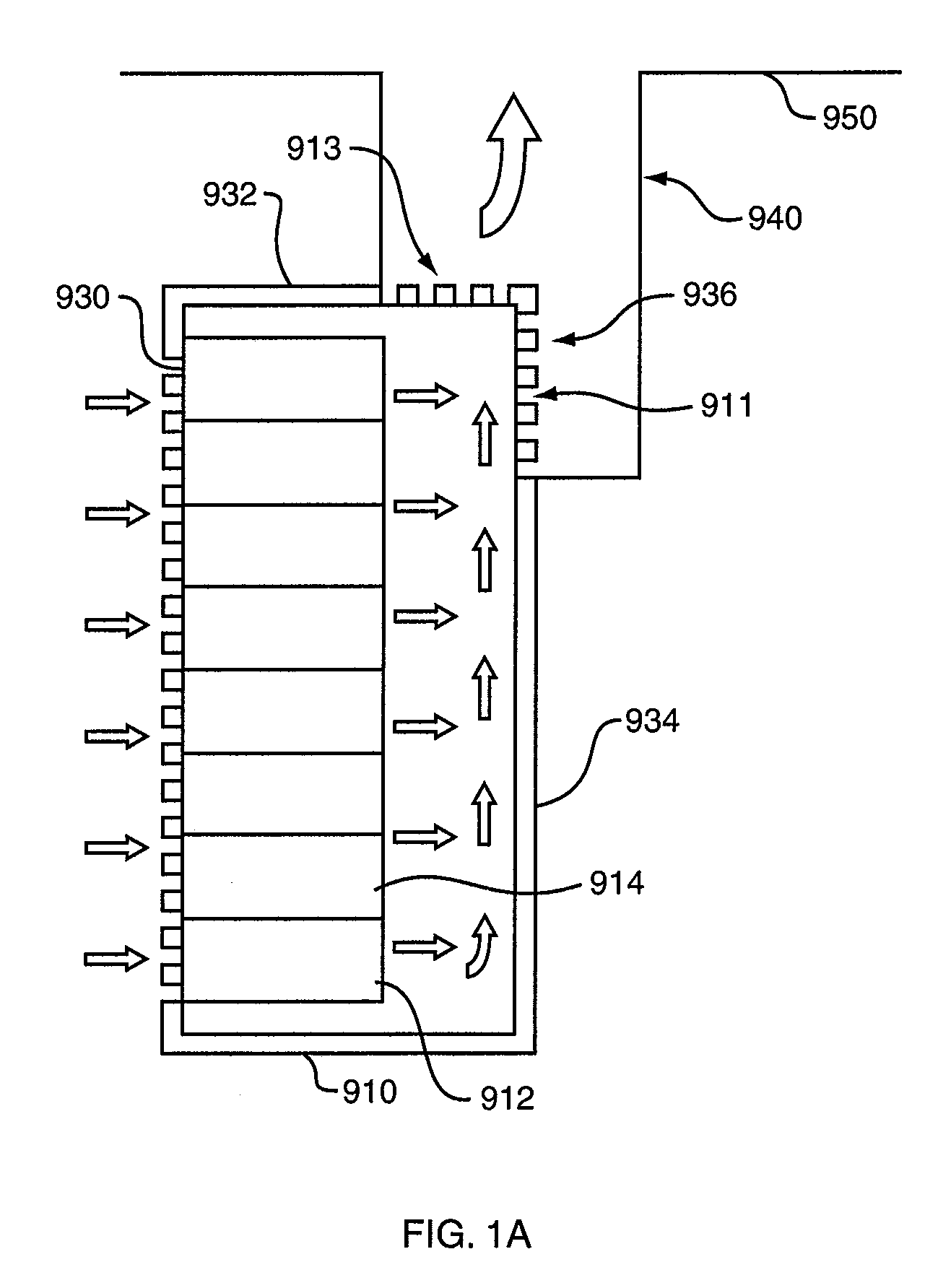
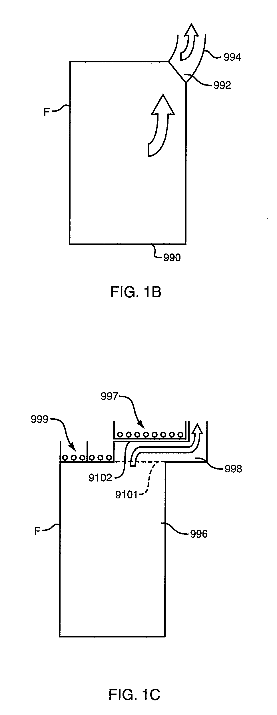
[0114]This invention may be accomplished in an assembly for extracting heat from a housing for electronic equipment, the housing having a front, a back, two sides and a top, the assembly comprising a back for the housing that defines an open area proximate the top, and an air passageway in fluid communication with the open area in the back, to conduct heated air exiting the housing through the open area away from the housing. Typically, the front is perforated and the sides are solid, so that air flows into the housing through the front, through the electronic equipment located in the housing, and out of the housing through the open area, into the passageway.

[0115]FIGS. 1A-1C schematically depict three concepts for accomplishing the invention, which is an assembly for extracting heat from a housing for electronic equipment. In this case, housing 910 may be a computer server rack such as a “Paramount” enclosure offered by Wright Line LLC of Worcester, Mass. Computer equipment rack 91...


PUM


Abstract

An assembly for supplying heated air to a housing with an interior that is adapted to hold air conditioning equipment. The housing has a top portion and a back portion, where the top portion defines a first opening that leads to the interior of the housing, and where the first opening is proximate the back of the top portion of the housing. The back portion of the housing defines a second opening that leads to the housing interior, where the second opening is proximate the top of the back portion. The assembly includes a flue external to the housing and adapted to be coupled to the housing such that the flue encompasses and is in fluid communication with the first and second openings, the flue defining an inlet for conducting heated air into the flue and an outlet for conducting heated air out of the flue and into the housing through the first and second openings. The air cooled by the air conditioning equipment in the housing is used to cool electronic equipment.

Description

CROSS-REFERENCE TO RELATED APPLICATIONS[0001]This application is a continuation-in-part of, and claims priority from, co-pending U.S. patent application Ser. No. 12 / 409,647, entitled “Assembly for Extracting Heat from a Housing for Electronic Equipment,” filed Mar. 24, 2009, and U.S. patent application Ser. No. 12 / 432,154, filed Apr. 29, 2009, entitled “Systems and Methods for Closed Loop Heat Containment with Cold Aisle Isolation for Data Center Cooling.” The entire contents of both applications are expressly incorporated herein.FIELD OF THE INVENTION[0002]This invention relates to an assembly for adapting in-row air conditioning units, such as those used in a data center, to draw heated air from a plenum or duct and provide cooled air to electronic equipment.BACKGROUND OF THE INVENTION[0003]Electronic equipment is often located within a housing, such as an equipment rack used to hold computer servers and the like in assemblies that are located within the rack. The electronic equip...

Claims


Application Information

Patent Timeline
Patent Type & Authority Applications(United States)
IPC IPC(8): H05K5/02F24D19/00F28D15/00F28F13/12
CPCH05K7/20745
Inventor TRESH, MICHAELJACKSON, BRIANBEDNARCIK, EDWARDPRUNIER, JOHNOLSEN, MARTINGERMAGIAN, MARKLUCIA, DAVID
Owner WRIGHT LINE
Why Eureka
Try Eureka