Zero Profile Spinal Fusion Cage

a cage and spinal fusion technology, applied in the field of zero-profile spinal fusion cages, can solve the problems of nerve irritation and pain, affecting the flow of waste products out of the disc, and causing the cell within the nucleus pulposus to emit toxic amounts of cytokines and mmps,

Active Publication Date: 2010-09-30
DEPUY SYNTHES PROD INC
View PDF120 Cites 218 Cited by
  • Summary
  • Abstract
  • Description
  • Claims
  • Application Information

AI Technical Summary

Problems solved by technology

In other instances of DDD, genetic factors or apoptosis can also cause the cells within the nucleus pulposus to emit toxic amounts of these cytokines and MMPs.
In some instances, the pumping action of the disc may malfunction (due to, for example, a decrease in the proteoglycan concentration within the nucleus pulposus), thereby retarding the flow of nutrients into the disc as well as the flow of waste products out of the disc.
This reduced capacity to eliminate waste may result in the accumulation of high levels of toxins that may cause nerve irritation and pain.
As DDD progresses, toxic levels of the cytokines and MMPs present in the nucleus pulposus begin to degrade the extracellular matrix, in particular, the MMPs (as mediated by the cytokines) begin cleaving the water-retaining portions of the proteoglycans, thereby reducing its water-retaining capabilities.
This degradation leads to a less flexible nucleus pulposus, and so changes the loading pattern within the disc, thereby possibly causing delamination of the annulus fibrosus.
These changes cause more mechanical instability, thereby causing the cells to emit even more cytokines, thereby upregulating MMPs.
As this destructive cascade continues and DDD further progresses, the disc begins to bulge (“a herniated disc”), and then ultimately ruptures, causing the nucleus pulposus to contact the spinal cord and produce pain.
This hardware adds to the time, cost, and complexity of the procedure.
It also can result in tissue irritation when the cage's profile extends out of the disc space, thereby causing dysphonia / dysphagia in the cervical spine and vessel erosion in the lumbar spine.
In addition, the fixation hardware typically includes a secondary locking feature, which adds to the bulkiness of the implant and time required for the procedure.
Furthermore, existing fixation hardware may prevent the implantation of additional hardware at an adjacent location, and so require removal and potentially extensive revision of a previous procedure.

Method used


Image

  • Zero Profile Spinal Fusion Cage
  • Zero Profile Spinal Fusion Cage
  • Zero Profile Spinal Fusion Cage

Examples


Embodiment Construction

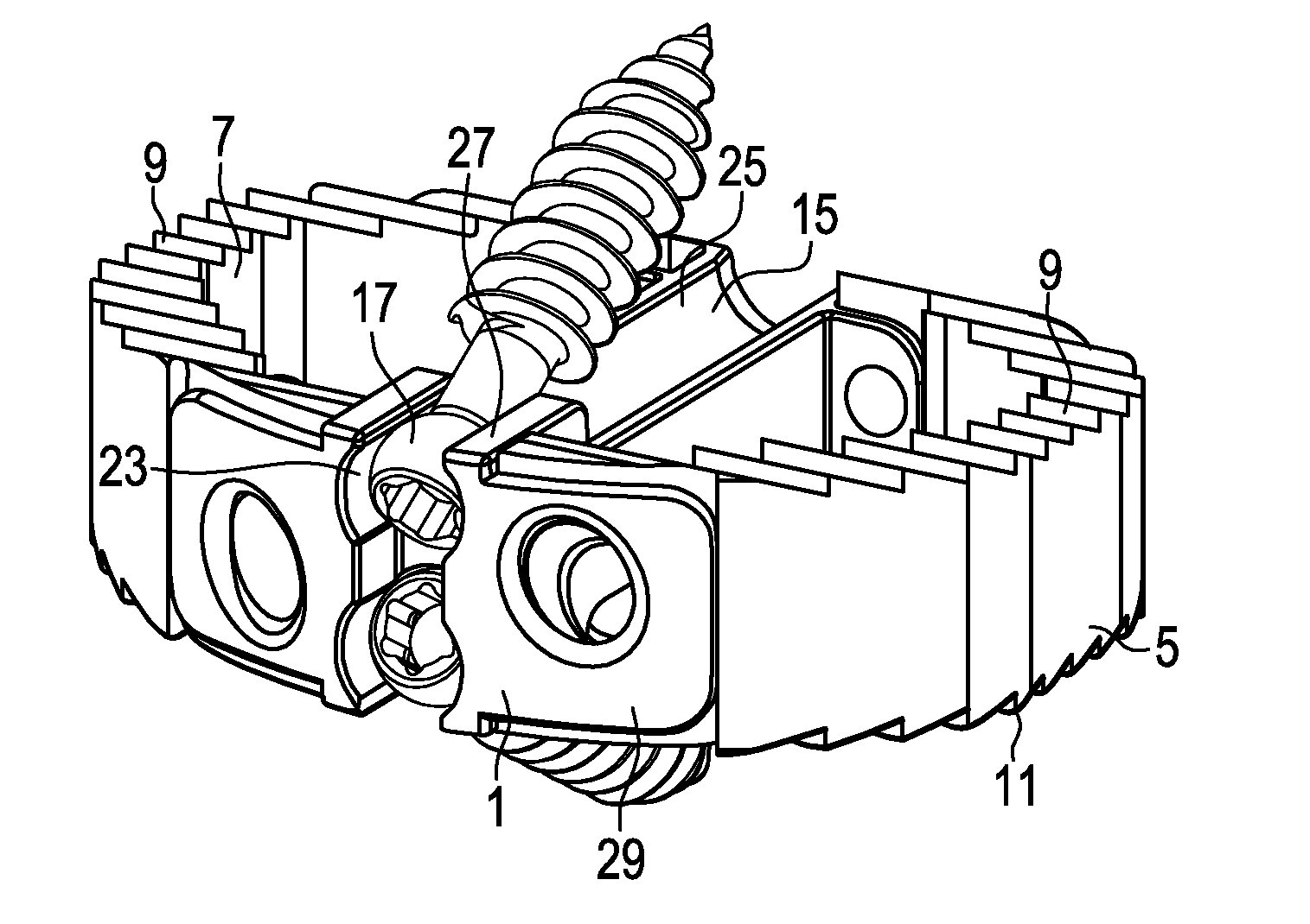
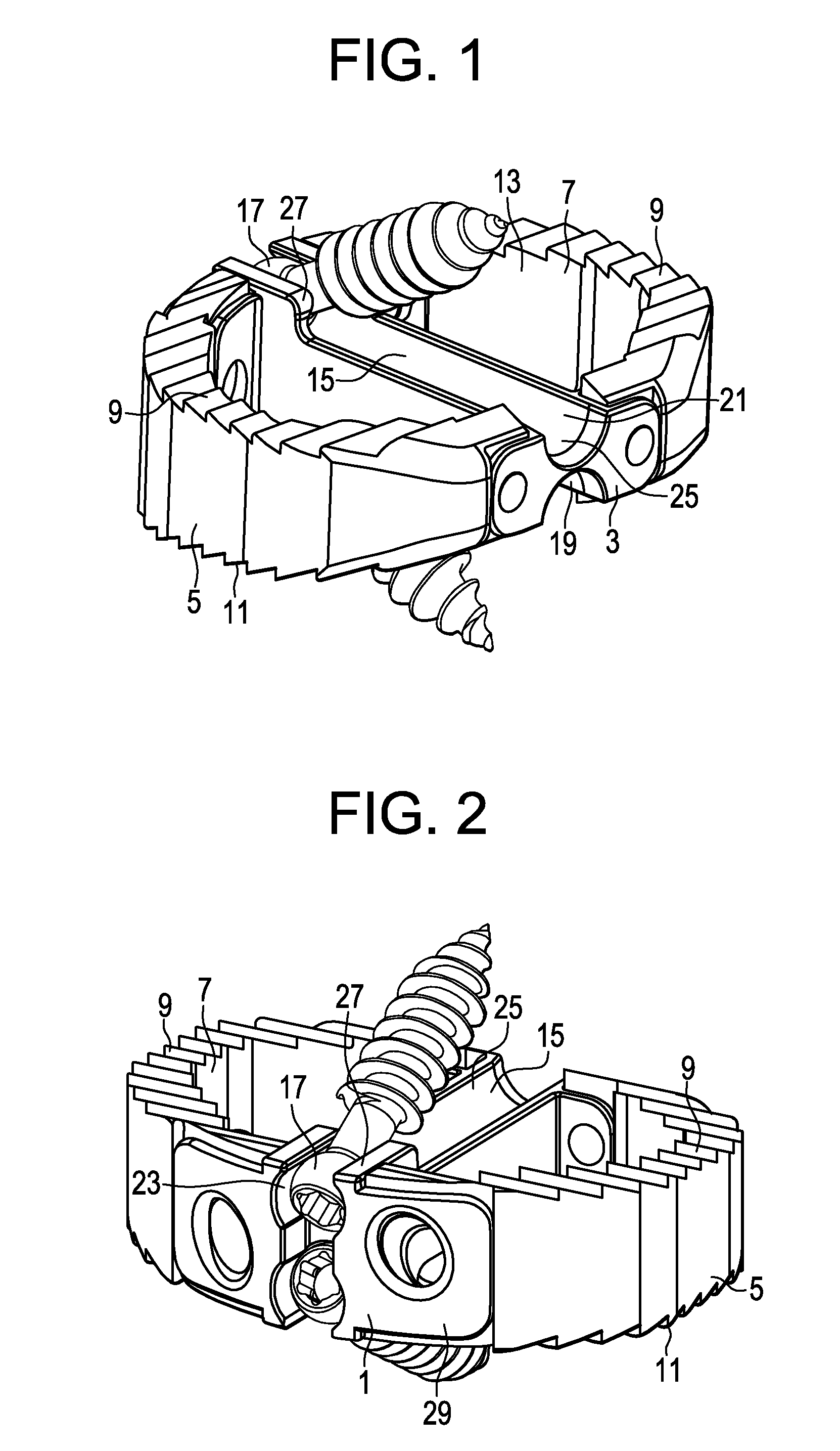
[0049]Now referring to FIGS. 1 and 2, there is provided an intervertebral fusion cage comprising:[0050]a) a proximal wall 1 and a distal wall 3,[0051]b) first 5 and second 7 side walls connecting the proximal and distal walls, an upper bearing surface 9 adapted for gripping an upper vertebral endplate and a lower bearing surface 11 adapted for gripping a lower vertebral endplate, the upper bearing surface having at least one upper opening 13 therethrough adapted to promote bony fusion, the lower bearing surface having at least one lower opening (not shown) therethrough adapted to promote bony fusion,[0052]c) a first guide surface depression 15 formed in the upper bearing surface and extending substantially from the proximal wall to the distal wall, the depression adapted for distal reception of a first screw head 17, and[0053]d) a second guide surface depression 19 formed in the lower bearing surface and extending substantially from the proximal wall to the distal wall, the second d...


PUM

PropertyMeasurementUnit
diameteraaaaaaaaaa
median lengthaaaaaaaaaa

Abstract

An interbody fusion cage having upper and lower canals for receiving the heads of bone screws that have been pre-installed in opposing vertebral body endplates. The proximal wall of the cage preferably has a vertical slot that communicates with each canal and is adapted to allow access by a screwdriver and tightening of the screws.

Description

BACKGROUND OF THE INVENTION[0001]The natural intervertebral disc contains a jelly-like nucleus pulposus surrounded by a fibrous annulus fibrosus. Under an axial load, the nucleus pulposus compresses and radially transfers that load to the annulus fibrosus. The laminated nature of the annulus fibrosus provides it with a high tensile strength and so allows it to expand radially in response to this transferred load.[0002]In a healthy intervertebral disc, cells within the nucleus pulposus produce an extracellular matrix (ECM) containing a high percentage of proteoglycans. These proteoglycans contain sulfated functional groups that retain water, thereby providing the nucleus pulposus within its cushioning qualities. These nucleus pulposus cells may also secrete small amounts of cytokines such as interleukin-1β and TNF-α as well as matrix metalloproteinases (“MMPs”). These cytokines and MMPs help regulate the metabolism of the nucleus pulposus cells.[0003]In some instances of disc degener...

Claims


Application Information

Patent Timeline
Patent Type & Authority Applications(United States)
IPC IPC(8): A61F2/44
CPCA61F2/30965A61F2310/00293A61F2/447A61F2/4611A61F2002/30062A61F2002/30596A61F2002/30604A61F2002/30794A61F2002/4475A61F2002/4622A61F2002/4627A61F2002/4628A61F2210/0004A61F2310/00017A61F2310/00023A61F2310/00029A61F2310/00203A61F2310/00239A61F2/4465A61F2310/00059A61F2310/00161A61F2002/30594A61F2002/3079A61F2002/30593A61B17/8042A61F2002/443A61F2/442A61F2/44A61F2/4425A61F2/446A61F2/4455A61F2/4684
Inventor SLIVKA, MICHAEL A.GRINBERG, ALEXANDERVOELLMICKE, JOHNHAWKINS, JOHN RILEY
Owner DEPUY SYNTHES PROD INC
Why Eureka
Try Eureka