
High Performance Resin Piston Internal Combustion Engine

a resin piston and internal combustion engine technology, applied in the direction of engines, cylinders, machines/engines, etc., can solve the problems of inability to provide adequate lubrication and sealing, and no one has proposed a polygonal profile design for the piston and cylinder in the internal combustion engin

Active Publication Date: 2010-10-07
DHARANI MURAD +1
View PDF24 Cites 6 Cited by
  • Summary
  • Abstract
  • Description
  • Claims
  • Application Information

AI Technical Summary

Benefits of technology

[0006]Accordingly, it is an object of this invention to provide a lightweight, durable, and efficient internal combustion engine, in which the pistons and engine block including cylinder walls, are formed of a high performance synthetic (composite) material, and which avoids the drawbacks of the prior art.
[0008]It is another feature to provide bearings in the walls of the cylinder to allow the piston to glide smoothly up and down in its stroke, and also to prevent compression from escaping.
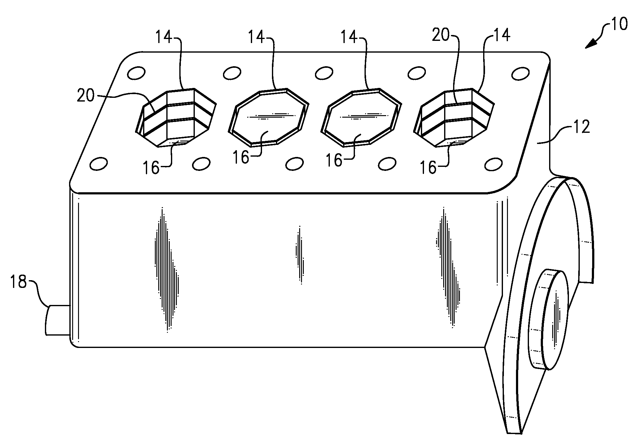
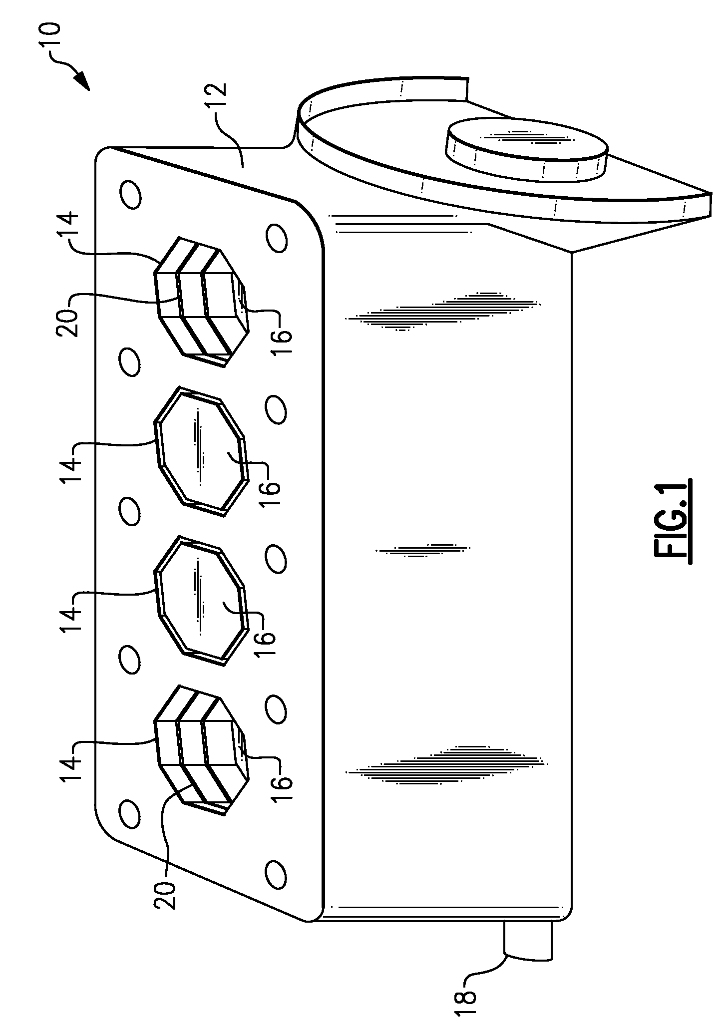
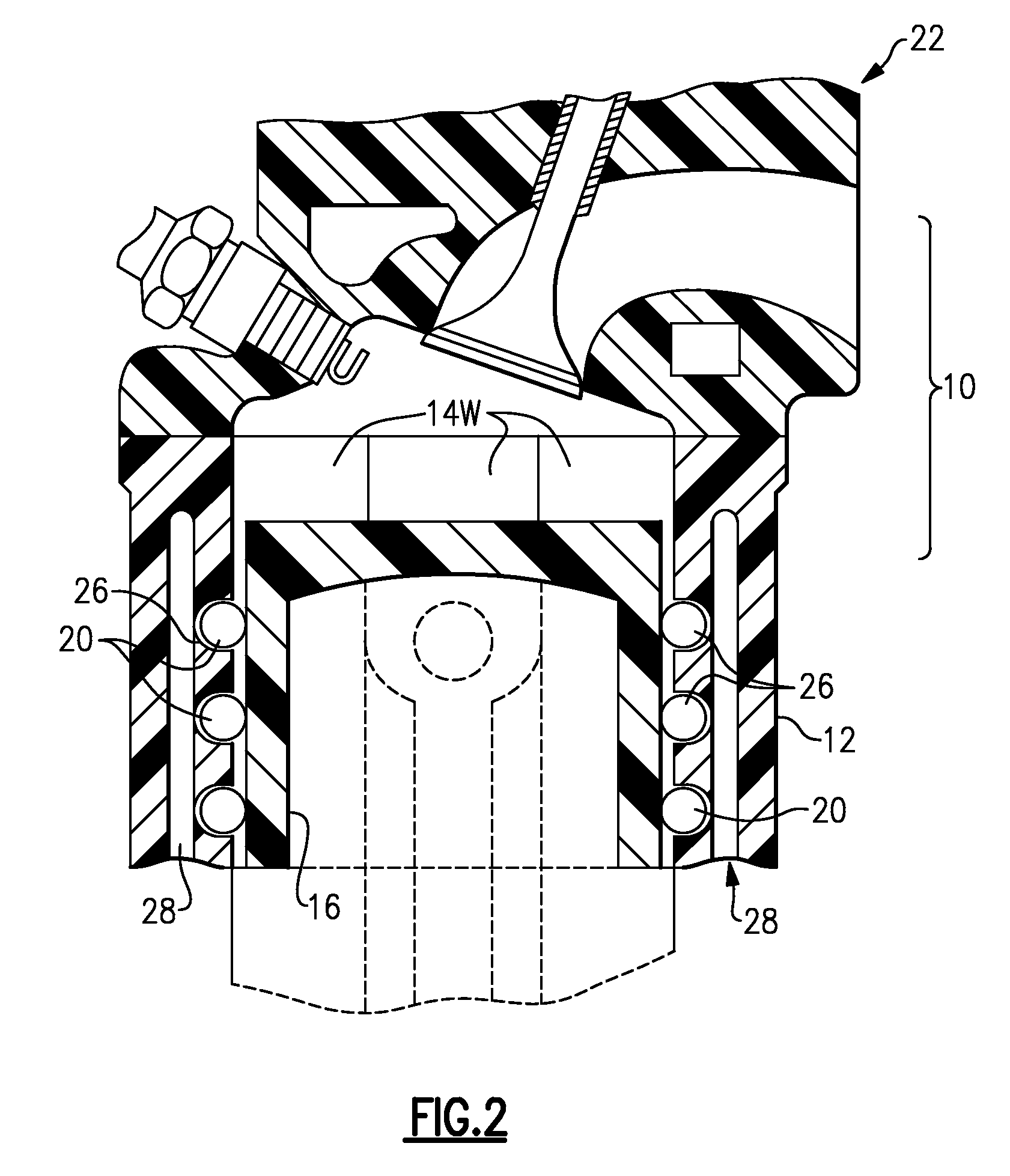
[0011]Transverse semi-cylindrical grooves are formed on the cylinder walls at respective axial levels on the wall sections, such that the grooves at each said level combine to form a polygonal (i.e., eight sided) annular channel, with each of these having an open side facing towards the associated piston. Preferably there are two annular channels at two levels, or three at three levels. Roller bearings are positioned in these transverse grooves, and these bear against the sides of the associated piston, to afford smooth, low-friction rolling contact and to seal the compression from leaking around the piston.
[0017]The position of the water cooling jacket within the block can be molded or formed at an optimum location near the upper parts of the cylinders. Additives or fillers can be present in the resin to increase thermal conductivity at the cylinder walls.

Problems solved by technology

To date, even though durable synthetic materials are available, no one has previously proposed an internal combustion engine in which the components that constitute the combustion chamber itself, i.e., the piston and the cylinder walls, are formed of one of these high performance synthetic resin materials.
However, with a traditional round-profile cylinder and piston construction, it is difficult to provide adequate lubrication and sealing.
However, to date, no one has proposed a polygonal profile design for a piston and cylinder in an internal combustion engine, nor associated with any device in which the piston and cylinder walls are formed of a synthetic or composite resin.

Method used


Image

  • High Performance Resin Piston Internal Combustion Engine
  • High Performance Resin Piston Internal Combustion Engine
  • High Performance Resin Piston Internal Combustion Engine

Examples


Embodiment Construction

)

[0028]With reference to the Drawing, and initially to FIG. 1, an embodiment of the invention is an internal combustion engine 10 constructed of a high performance composite resin. FIG. 1 shows an engine block 12 (with portions such as head, oil pan, gear covers etc omitted in this view), with a number of octagonal cylinders 12, each of which houses a reciprocating piston 14, of a mating octagonal profile. A crank 18 is housed in the engine block 12. There are threaded holes shown here for mounting the cylinder head. Not shown here are cavities molded within the block for the circulation of an engine coolant. In this view, the number two and three cylinders are shown with their pistons 16 at top dead center, and the number one and four cylinders with their pistons 16 at bottom dead center. Within the latter cylinders can be seen transverse roller pin bearings 20 placed at two levels along the upper part of the flat cylinder wall portions of each octagonal cylinder. These will be des...


PUM


Abstract

A piston-type internal combustion engine is formed of a high performance synthetic resin material. The cylinders and pistons have an octagonal profile. Two or three rows of pin roller bearings are positioned in transverse semi-cylindrical grooves formed on the cylinder walls, to afford smooth, low-friction rolling contact and to seal the compression from leaking around the piston. There are angle support pieces fitted within the annular channels at respective vertices or corners, and are adapted for rotationally supporting the ends of adjacent pin roller bearings.

Description

BACKGROUND OF THE INVENTION[0001]This invention relates to reciprocating internal combustion engines, such as diesel, gasoline or natural gas powered engines, and is more specifically directed to an internal combustion engine whose major parts, including cylinder block and pistons, are made of a high performance synthetic resin material.[0002]An effort has been made to reduce the design weight of automotive engines, or other engines, and at the same time to increase efficiency and longevity. To this end, synthetic materials have been used in such engine parts as oil pans, valve covers, gear covers, cranks, and some internal parts such as rocker arms and connecting rods. One composite engine block, in which an outer shell is formed of a synthetic material, with cylinder sleeves formed of cast iron and with metal pistons, is described in U.S. Pat. No. 4,930,470. U.S. Pat. No. 4,440,069 discusses a composite piston for an internal combustion engine, in which the piston has a metal head...

Claims


Application Information

Patent Timeline
Patent Type & Authority Applications(United States)
IPC IPC(8): F02F3/00F16J9/00F02F7/00
CPCF02F1/18F05C2253/20F02F3/0084
Inventor DAUPHIN, MICHEL
Owner DHARANI MURAD
Learn More