
Method for operating a rotating electric machine

a technology of rotating electric machines and electric motors, applied in the direction of electronic commutators, motor/generator/converter stoppers, dynamo-electric converter control, etc., can solve the problems of power semiconductor switches that can age more quickly, heat loss, and increased energy consumption

Inactive Publication Date: 2010-10-07
ABB RES LTD
View PDF4 Cites 8 Cited by
  • Summary
  • Abstract
  • Description
  • Claims
  • Application Information

AI Technical Summary

Benefits of technology

[0073]The exemplary use of the FPGA for method steps (d), that is to say for method steps (b) and (c) and for method steps (f) to (k), can result in the digital signal processor which is used, and is used for method step (e1), being used only for the calculation steps which are desired for step (e1) of the method, as a result of which step (e1) can involve a short computation time. The state intermediate value sets which are calculated in step (e1) can therefore be available after only a very short time and can then be used further directly by the FPGA, for example in method steps (d), that is to say for method steps (b) and (c) and for method steps (e2) to (k), in which case the FPGA can likewise process these method steps in a very short time, for example, by its capability for parallel calculation of serial calculation sequences. Overall, the use of the FPGA in conjunction with the digital signal processor can make it possible to keep the computation time for the calculation steps of the method, and therefore the execution time for the method steps, short, as a result of which the connection of the phases of the converter circuit to the DC voltage circuit can take place in good time according to the selected switching state combination of switching states of the power semiconductor switches.
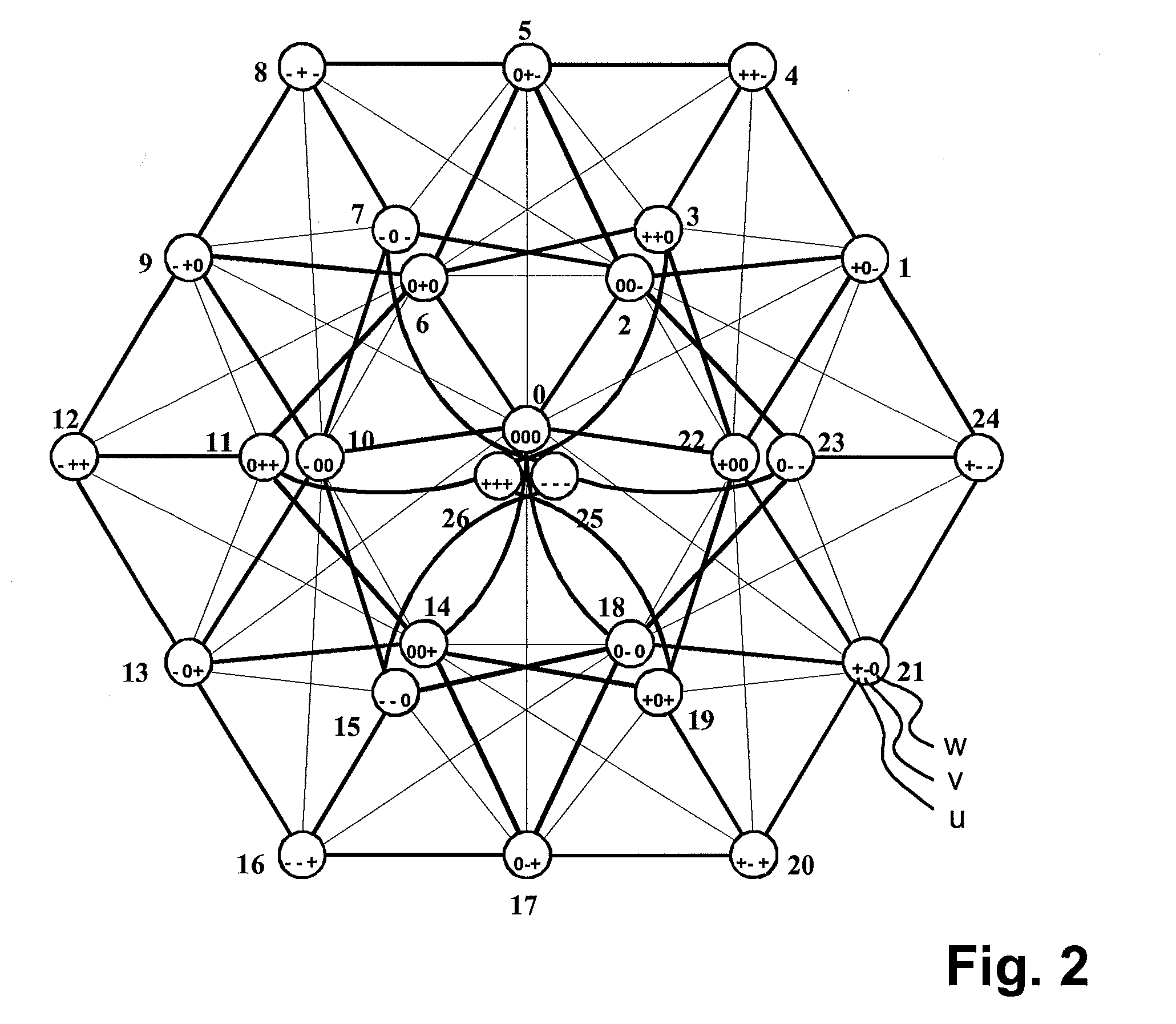
[0076]Steps (l) to (o) can result in the optimum switching state combination being selected in the situation in which the respectively associated torque trajectory or the magnetic stator flux trajectory is outside the predetermined value range. Exemplary methods according to the disclosure are therefore able to handle switching state combinations with a respectively associated torque trajectory and magnetic stator flux trajectory which are outside the predetermined value range. This can allow unrestricted operation of the rotating electrical machine.

Problems solved by technology

However, a high switching frequency such as this can result in heat losses (greater energy consumption) in the power semiconductor switches in the converter circuit, as a result of which the power semiconductor switches can age more quickly, may be damaged, or may even be destroyed.
The multiplicity of calculation steps in the method according to EP 1 670 135 A1 involves computation power for a digital signal processor, thus resulting in very long computation times in the digital signal processor, and therefore also long execution times for the method steps, which can then result in the phases of the converter circuit being connected at the wrong time to the DC voltage circuit according to the selected switching state combination of switching states of the power semiconductor switches.
However, only restricted operation of the rotating electrical machine is therefore possible.

Method used


Image

  • Method for operating a rotating electric machine
  • Method for operating a rotating electric machine
  • Method for operating a rotating electric machine

Examples


Embodiment Construction

[0046]A method is disclosed for operating a rotating electrical machine, such that the computation time for the calculation steps of the method, and therefore the execution time for the method steps, are relatively short (e.g., as short as possible), and which method can handle switching state combinations with an associated torque trajectory and a magnetic stator flux trajectory, which torque trajectory or magnetic stator flux trajectory are outside a predetermined value range.

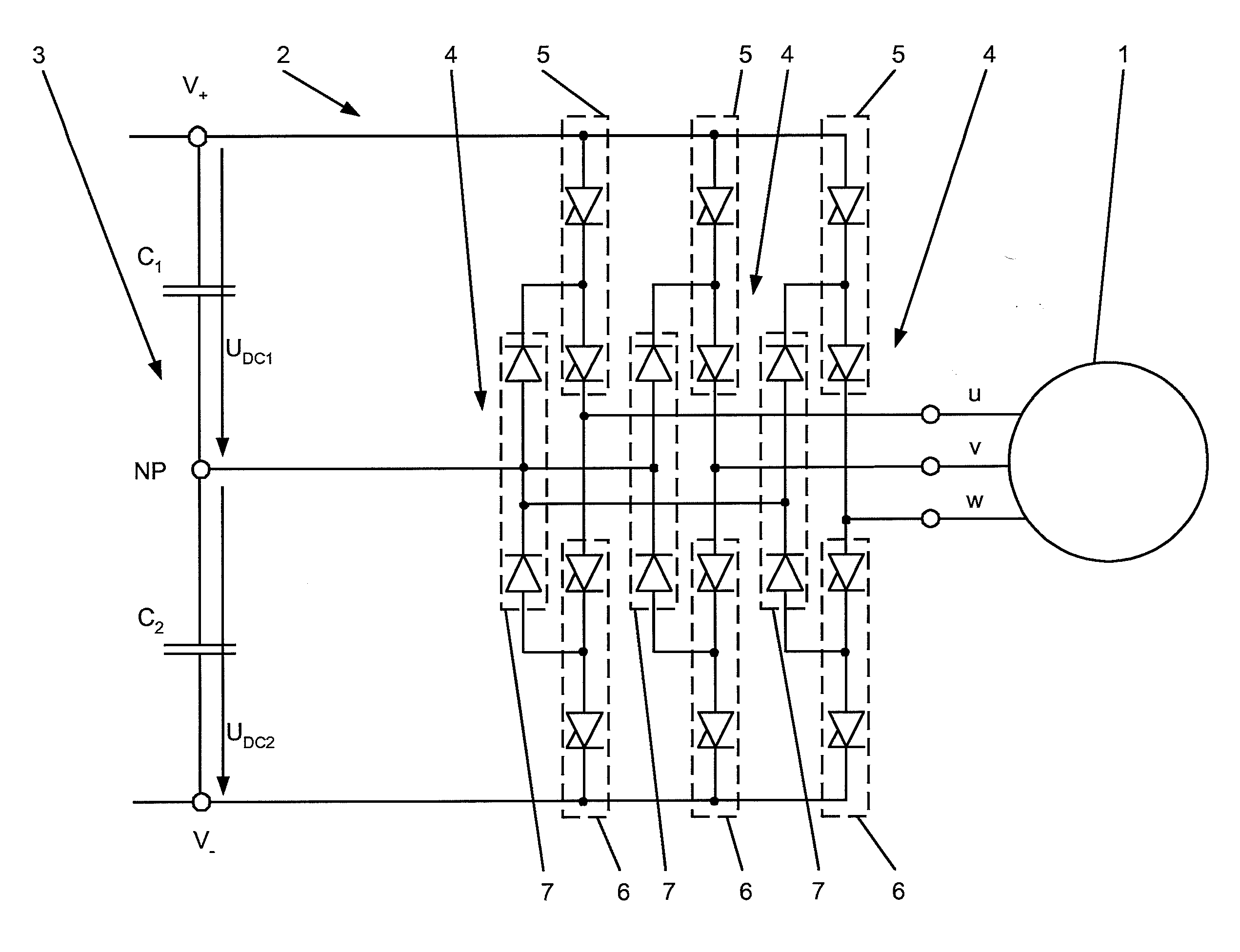
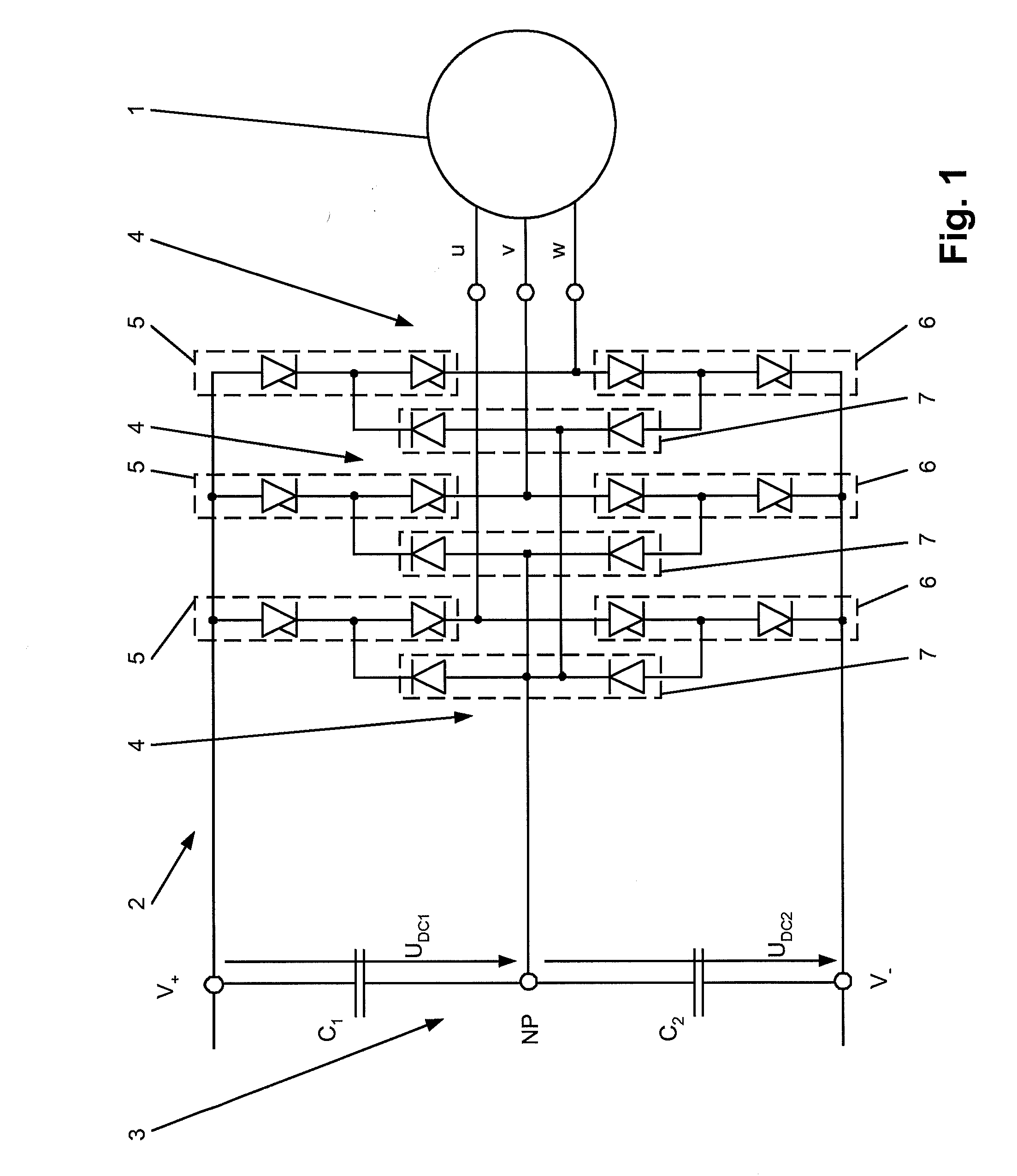
[0047]In an exemplary method according to the disclosure for operating a rotating electrical machine, the rotating electrical machine is connected phase-by-phase to a converter circuit, which has a DC voltage circuit, for switching m voltage levels, where m≧2. According to the method, in a step (a), the phases of the converter circuit are connected to the DC voltage circuit in accordance with a selected switching state combination of switching states of power semiconductor switches in the converter circuit.

[0...


PUM


Abstract

A method is disclosed for operating a rotating electric machine, wherein the rotating electric machine is connected by phases to a converter circuit having a direct-current circuit for switching at least two voltage levels, and the phases of the converter circuit are connected to the direct-current circuit according to a selected switch state combination of switch states of power semi-conductor switches of the converter circuit. Exemplary embodiments can reduce the switching frequency of the power semi-conductor switches, based on a prediction of further behavior of the overall system, and selection of an optimum switching state combination.

Description

RELATED APPLICATIONS[0001]This application claims priority as a continuation application under 35 U.S.C. §120 to PCT / EP2008 / 065354, which was filed as an International Application on Nov. 12, 2008 designating the U.S., and which claims priority to European Application 07150189.4 filed in Europe on Dec. 20, 2007. The entire contents of these applications are hereby incorporated by reference in their entireties.FIELD[0002]The disclosure relates to the field of operating rotating electrical machines.BACKGROUND INFORMATION[0003]High-power voltage-converter circuits are used in many applications. Known converter circuits have three voltage levels and are used for operating rotating electrical machines, such as synchronous and asynchronous machines, which rotating electrical machines can have three stator windings. In a known method for operating a rotating electrical machine, the machine is connected phase-by-phase to a converter circuit such as this, which has a DC voltage circuit, for ...

Claims


Application Information

Patent Timeline
IPC IPC(8): H02P7/06
CPCH02P23/004H02P21/0035H02P23/30H02P21/22
Inventor PAPAFOTIOU, GEORGIOSZURFLUH, FRANZ
Owner ABB RES LTD
Learn More