
Efficient power regulation for class-e amplifiers

a power regulation and amplifier technology, applied in the direction of electric variable regulation, process and machine control, instruments, etc., can solve the problems of increasing harmonic distortion, reducing efficiency or both, and increasing harmonic distortion

Inactive Publication Date: 2010-10-07
MAXIM INTEGRATED PROD INC
View PDF32 Cites 39 Cited by
  • Summary
  • Abstract
  • Description
  • Claims
  • Application Information

AI Technical Summary

Benefits of technology

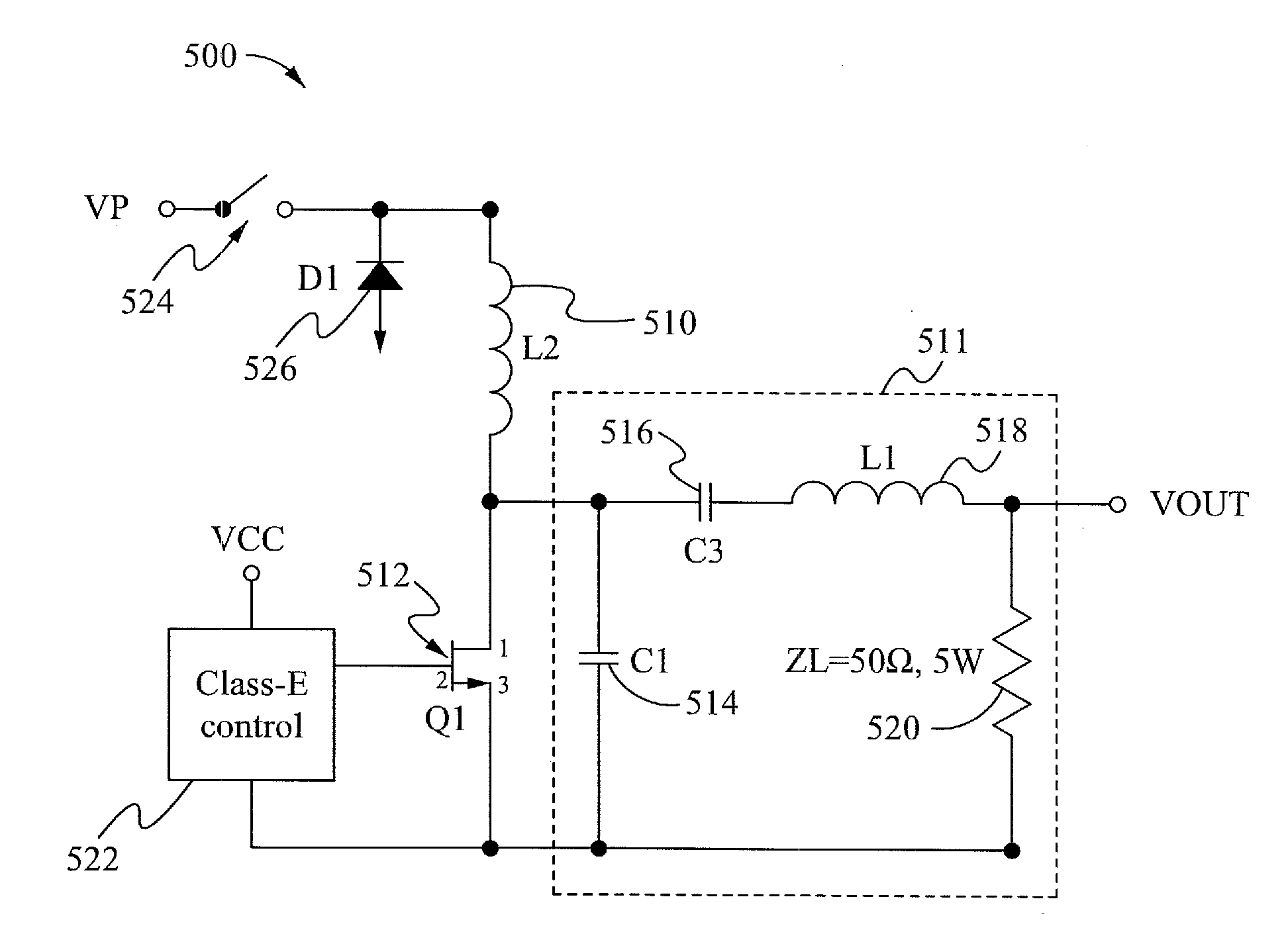
[0014]In accordance with a first aspect of the present invention, a power converter device is provided. The power converter device includes an input power source. An input inductor is configured for coupling a power of the input power source to the device. A switch is configured to regulate a power of the input power source through the input inductor to adjust an output voltage of the device. A shunting diode is coupled between the switch and the input inductor. A resonant load is coupled with the input inductor comprising a first capacitor, a second capacitor, a series inductor and a load circuit. A switching element is coupled with the input inductor and the resonant load and is configured to operate at a fixed frequency. The power converter device also includes a control circuit for modulating a frequency of the switch and includes a driving module for driving the switching element at the fixed frequency.

Problems solved by technology

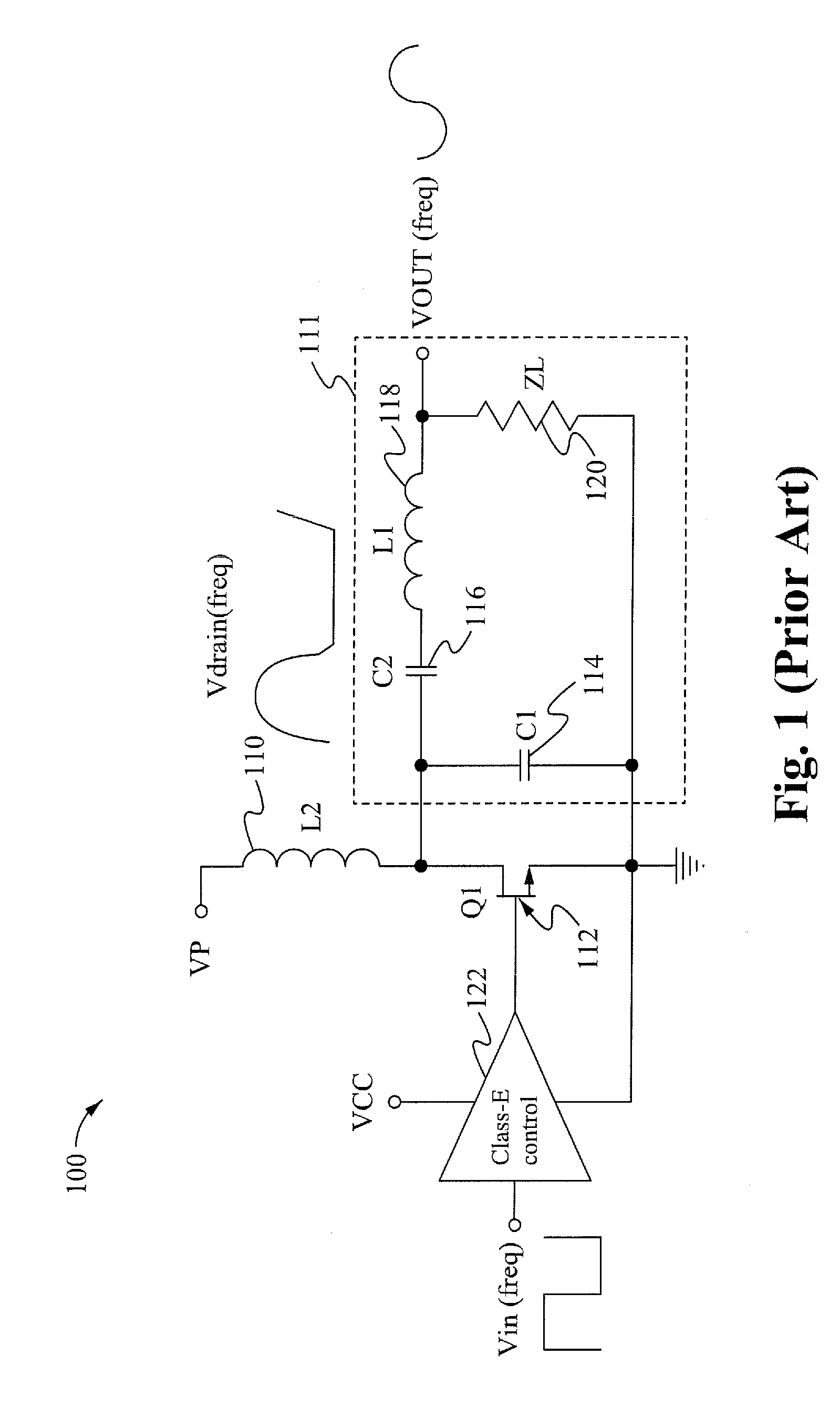
Deviating from this fixed relation results in an increase of undesired harmonic distortion or reduced efficiency or both.
Hence, devices similar to the device 100, attempting to effect the amplitude of the output VOUT by regulating the duty cycle of the input frequency, or by varying the LCR values will be subject to this increased harmonic distortion and reduced efficiency.
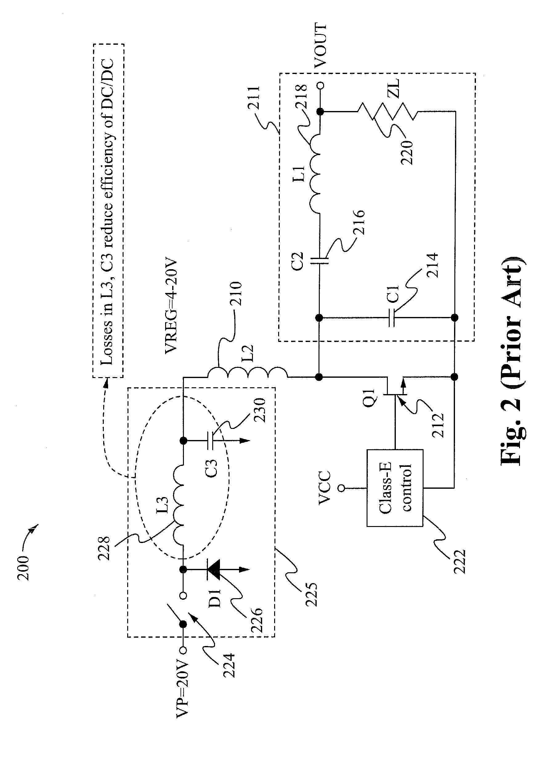
Additionally, the buck converter 225 requires additional discrete components which will increase the cost and complexity of the circuit 200.
Deviating from this fixed relation results in an increase of undesired harmonic distortion or reduced efficiency or both.
Hence, devices similar to device 300, attempting to effect the amplitude of the output VOUT by regulating the duty cycle of the input frequency, or by varying the LCR values will be subject to this increased harmonic distortion and reduced efficiency.
Additionally, the buck converter 225 requires additional discrete components which will increase the cost and complexity of the circuit 400.

Method used


Image

  • Efficient power regulation for class-e amplifiers
  • Efficient power regulation for class-e amplifiers
  • Efficient power regulation for class-e amplifiers

Examples


Embodiment Construction

[0031]In the following description, numerous details and alternatives are set forth for the purpose of explanation. However, one of ordinary skill in the art will realize that the invention can be practiced without the use of these specific details. In other instances, well-known structures and devices are shown in block diagram form in order not to obscure the description of the invention with unnecessary detail.

[0032]The present invention provides a power converting circuit with an increased efficiency of Class-E amplifiers and power converters. The present invention provides optimization of power transferred to a load circuit. The present invention also provides a savings of an inductor and capacitor from a customer bill of materials for each device made according to the invention. The present invention is a significant improvement over conventional Class-E amplifiers that use conventional buck converter circuits.

[0033]Turning to FIG. 5, a schematic diagram of a power converting ...


PUM


Abstract

A power converter device and method are provided. The power converter device includes an input power source and an input inductor configured for coupling a power of the input power source to the device. A switch is configured to regulate a power of the input power source through the input inductor. A shunting diode is coupled between the switch and the input inductor. A resonant load is coupled with the input inductor. A switching element is coupled with the input inductor and the resonant load and configured to operate at a fixed frequency. The power converter device also includes a control circuit for modulating a frequency of the switch and a driving module for driving the switching element at the fixed frequency. In an exemplary embodiment, the power converter device is a Class-E amplifier. The fixed frequency is a frequency equal to a resonant frequency of the resonant load. In one embodiment, the power converter device is configured as an integrated circuit device.

Description

FIELD OF THE INVENTION[0001]The present invention relates to the field of power amplifiers. More particularly, the present invention relates to Class-E power amplifiers and power converter devices.BACKGROUND[0002]A Class-E amplifier converts a DC source to an amplified output signal that is sinusoidal, at a certain frequency. Class-E amplifiers are typically highly efficient switching power amplifiers.[0003]FIG. 1 shows a conventional Class-E amplifier device 100. The device 100 includes an input power VP. A first terminal of an input inductor 110 is coupled to the input power VP. A drain of a MOSFET 112 is coupled with a second terminal of the input inductor 110 and an input terminal of a resonant LCR load or resonant load 111 having a resonant frequency. A driving module 122 is coupled with a gate of the MOSFET 112 for driving the MOSFET 112. The driving module 122 alternatively turns the MOSFET 112 on and off at a fixed frequency in response to an input signal ‘Vin(freq)’. The fi...

Claims


Application Information

Patent Timeline
Patent Type & Authority Applications(United States)
IPC IPC(8): G05F3/02
CPCH02M7/537Y02B70/1441H03F3/2176H03F1/0211Y02B70/10
Inventor FONDERIE, MAARTEN JEROEN
Owner MAXIM INTEGRATED PROD INC
Learn More