Electronic device and method for dc-dc conversion with slope compensation

Active Publication Date: 2010-10-07
TEXAS INSTR INC
View PDF9 Cites 39 Cited by
  • Summary
  • Abstract
  • Description
  • Claims
  • Application Information

AI Technical Summary

Benefits of technology

[0023]The electronic device and the methods according to the invention provide robust and accurate solutions for generating optimal slope compensation over a wide range of external conditions. Compared with prior art DC-DC converters using bipola

Problems solved by technology

Peak-sensing converters usually show inherent open loop instability above 50% duty cycle, a non-ideal loop response, a tendency towards subharmonic oscillation and noise sensitivity when the inductor ripple is small.
This situation can lead to instability.
This is sub-optimal as the convert

Method used


Image

  • Electronic device and method for dc-dc conversion with slope compensation
  • Electronic device and method for dc-dc conversion with slope compensation
  • Electronic device and method for dc-dc conversion with slope compensation

Examples


Example

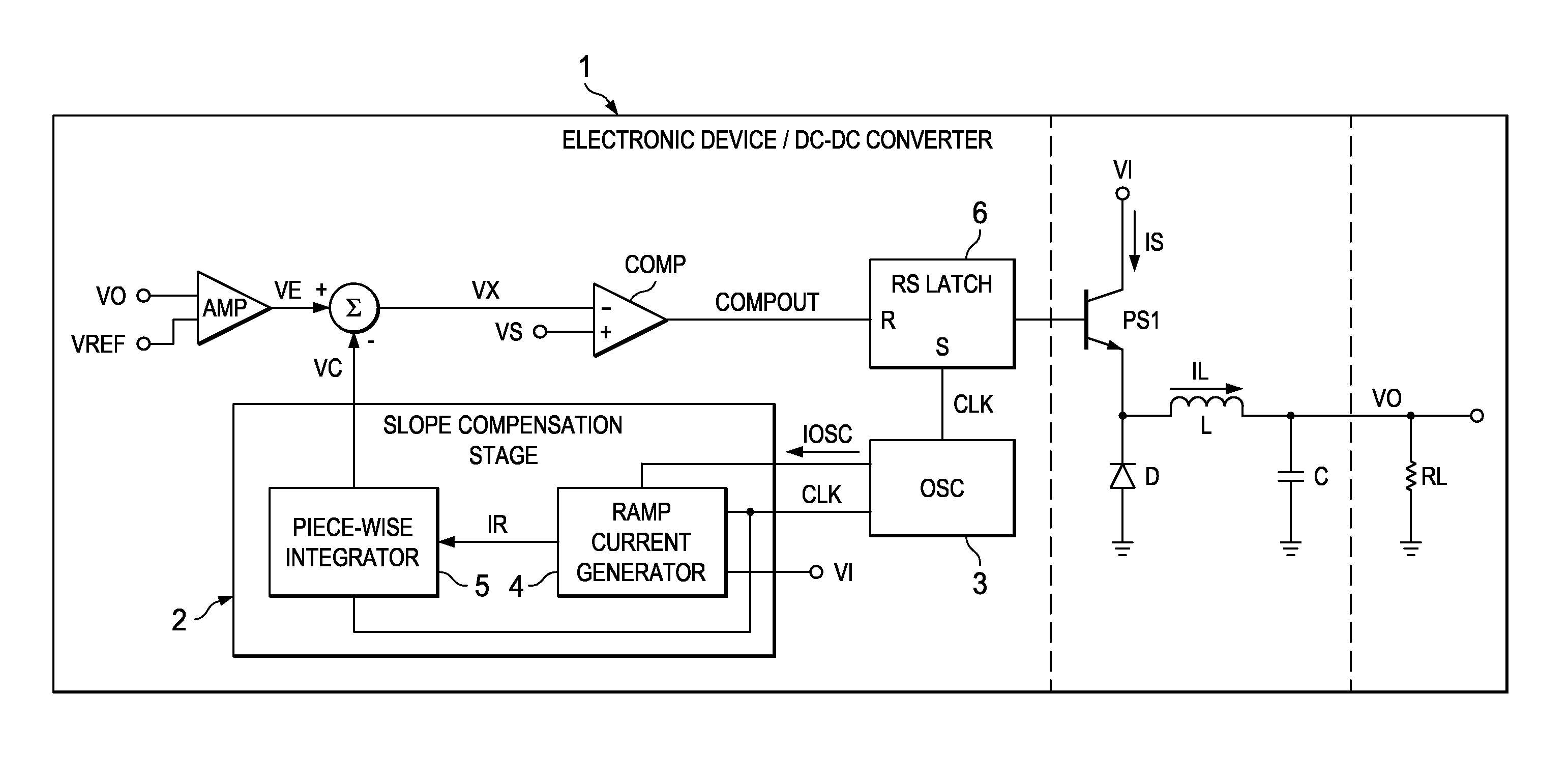
[0034]FIG. 4 shows a simplified circuit diagram of an embodiment of the invention. The dashed lines suggest different configurations for integrated and external components if the electronic device is—at least partially—implemented as an integrated circuit. In one embodiment, even the load may be integrated. In other embodiments, the load may be an external component. In another embodiment, the integrated circuit may be configured to include all necessary components to provide the control signals for the power transistor or several power transistors. Other configurations are conceivable.

[0035]The error amplifier AMP provides an error voltage VE by comparing the output voltage VO with a reference voltage VREF. A slope compensation VC is generated with slope compensation stage 2, which is implemented in accordance with aspects of the invention. For example, the input voltage may vary from 4V-40V and the frequency may vary between 150 KHz and 600 KHz. This may entail up to 100 times var...


PUM


Abstract

An electronic device is provided which comprises circuitry for DC-DC conversion configured to switch an inductor current through an inductor using slope compensation, wherein the circuitry comprises a slope compensation stage configured to generate a slope compensation signal as a function of an switching frequency of the DC-DC conversion and an input voltage of the DC-DC converter.

Description

CROSS-REFERENCE TO RELATED APPLICATIONS[0001]This patent application claims priority from German Patent Application No. 10 2009 016 290.9, filed Apr. 3, 2009, which is incorporated herein by reference in its entirety.FIELD OF THE INVENTION[0002]The present invention relates to an electronic device with circuitry for DC-DC conversion and a method.BACKGROUND OF THE INVENTION[0003]DC-DC converters have two basic control mechanisms: voltage and current control. Although the advantages of current-mode control over conventional voltage mode control have often been demonstrated, the typical peak-sensing current mode converter has several drawbacks. Peak-sensing converters usually show inherent open loop instability above 50% duty cycle, a non-ideal loop response, a tendency towards subharmonic oscillation and noise sensitivity when the inductor ripple is small. Most or all of these problems can be reduced or even overcome with a technique referred to as slope compensation.[0004]FIG. 1 show...

Claims


Application Information

Patent Timeline
IPC IPC(8): G05F3/02
CPCH02M3/156
Inventor HERZER, STEFANKULKARNI, SUMEET P.NEIDHARDT, JOCHENJANKOWSKI, MACIEJ
Owner TEXAS INSTR INC
Why Eureka
Try Eureka