Control device for electric rotating machine

a control device and rotating machine technology, applied in the direction of electric generator control, dynamo-electric converter control, dynamo-electric gear control, etc., can solve the problem of high difficulty in predicting current with high precision, and achieve the effect of high precision

Active Publication Date: 2010-10-14
DENSO CORP
View PDF3 Cites 61 Cited by
  • Summary
  • Abstract
  • Description
  • Claims
  • Application Information

AI Technical Summary

Benefits of technology

[0011]An object of the present invention is to provide, with due consideration to the drawbacks of the conventional control device, a control device which controls a controlled variable of an electric rotating machine while predicting the controlled variable according to a model of prediction-based control with high precision.

Problems solved by technology

Therefore, assuming that the prediction of the predicting unit is performed regardless of the polarity of the current, it is difficult to predict the current with high precision.

Method used


Image

  • Control device for electric rotating machine
  • Control device for electric rotating machine
  • Control device for electric rotating machine

Examples


first embodiment

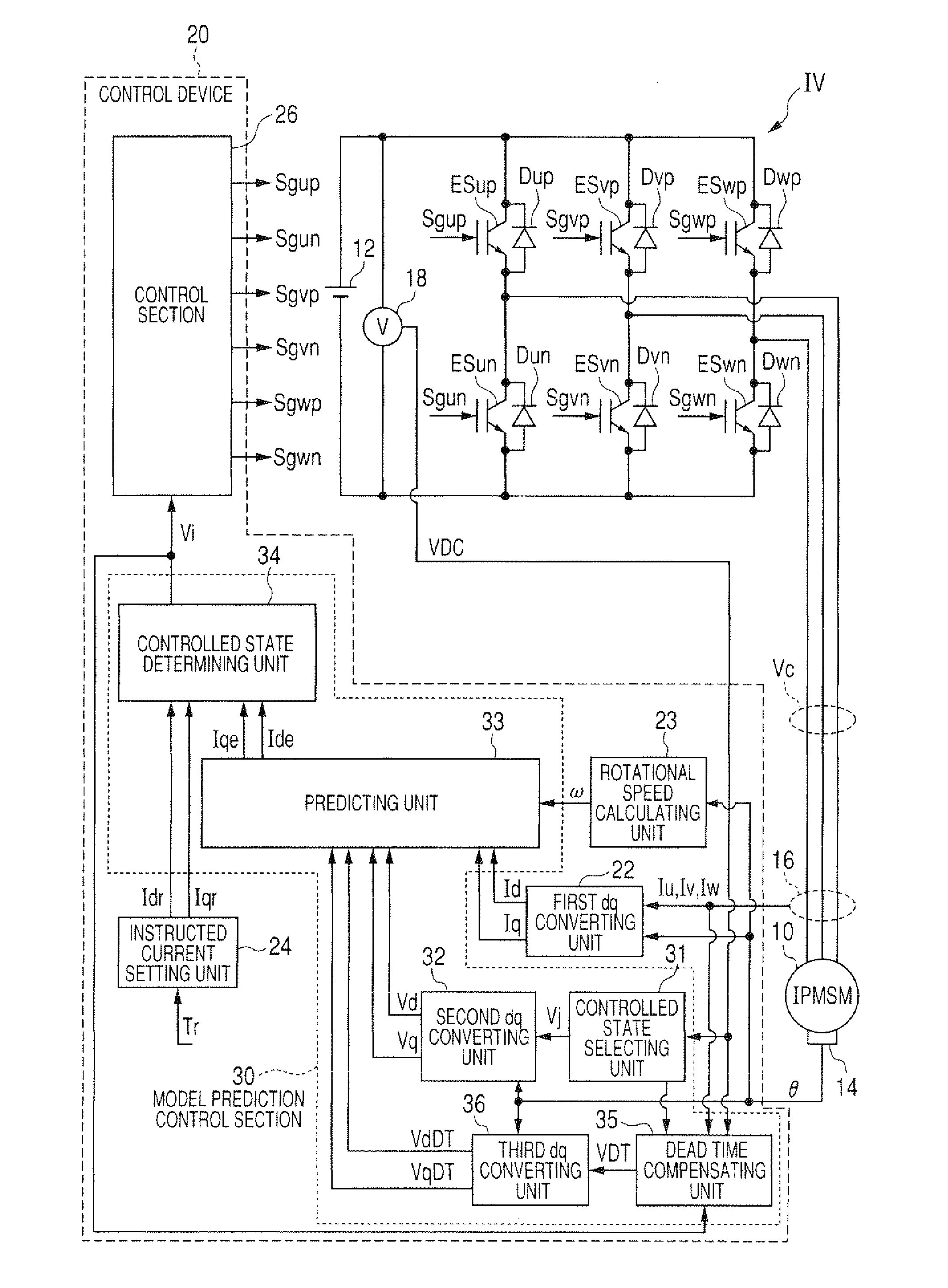
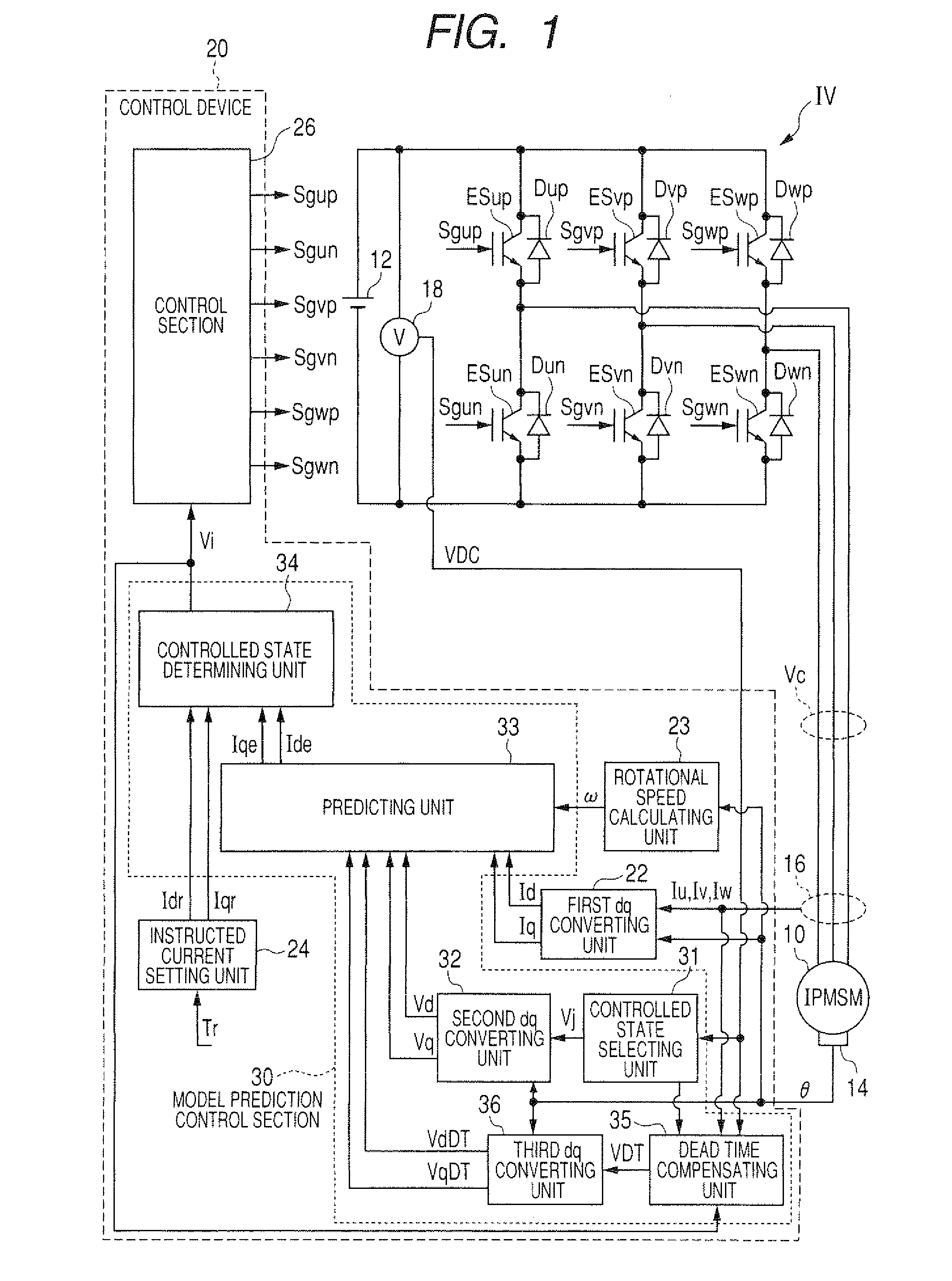
[0036]FIG. 1 is a view showing the structure of a control system having a control device for a motor generator according to the first embodiment.

[0037]As shown in FIG. 1, a high-voltage battery 12 supplies a direct current to a control system 11, the control system 11 converts this direct current into an alternating current of a controlled voltage Vc, and a motor generator 10 is driven by this alternating current to produce a driving torque. This power generating system including the generator 10, the system 11 and the battery 12 is, for example, mounted on a hybrid vehicle. The generator 10 represents an electric rotating machine whose feature is the presence of magnetic saliency. More specifically, the generator 10 is a three-phase interior permanent magnet synchronous motor (IPMSM). This motor has a rotor, permanent magnets having salient poles and being disposed around a shaft of the rotor so as to be protruded from the shaft, a stator surrounding the rotor, and three windings (...

second embodiment

[0089]In this embodiment, the compensating unit 35 determines the voltage vector VDT set in the dead time DT according to specific control logic without using the map shown in FIG. 5.

[0090]FIG. 8 is a block diagram of the compensating unit 35 according to the second embodiment.

[0091]As shown in FIG. 8, the compensating unit 35 has a state difference judging block 35a that judges whether or not each voltage component of the voltage vector Vj(n) selected in the selecting unit 31 differs from the corresponding voltage component of the voltage vector V(n−1), determined in the unit 34 in the preceding control period so as to be set in the inverter IV in the state setting time of the present control period, a current polarity judging block 35b that judges a polarity of each phase current, flowing through the generator 10 at the present time, from the flow direction of the current, and a dead time voltage vector calculating block (i.e., an intermediate voltage vector calculating block) 35c...

third embodiment

[0104]FIG. 11 is a view showing the structure of a control system having a control device according to the third embodiment. As shown in FIG. 11, a control device 20A according to this embodiment differs from the control device 20 shown in FIG. 1 in that the device 20A has a dead time compensating unit (i.e., a polarity judging unit) 41 in place of the units 35 and 36.

[0105]On the assumption that there is no period of the dead time DT in the control period ΔT, the predicting unit 33 predicts a base value Idbe(n+1) of the d-axis current Ide(n+1) and a base value Iqbe(n+1) of the q-axis current Iqe(n+1) according to equations (c7) and (c8).

Idbe(n+1)=Id(n)+[ΔT{−RId(n)+ωLqIq(n)}+ΔTVd] / Ld  (c7)

Iqbe(n+1)=Iq(n)+[ΔT{−RIq(n)−ωLdId(n)−ωφ}+ΔTVq] / Lq  (c8)

[0106]These equations (c7) and (c8) are obtained by setting the dead time DT at zero in the respective equations (c5) and (c8).

[0107]To compensate for the difference between the controlled state (i.e., the voltage vector) determined in the unit...


PUM


Abstract

A control device has a unit for selecting each of controlled voltages outputted from an inverter to a generator, a unit for judging a polarity of a current flowing through the generator, a unit for predicting a current of the generator from each selected voltage to be outputted from the inverter in the succeeding period, while performing the prediction based on the current polarity each time the selected voltage differs from the voltage already outputted from the inverter in the present period, a unit for determining one voltage corresponding to one predicted current nearest to an instructed current among the predicted currents, and a unit for controlling the generator by controlling the inverter to change the voltage already outputted from the inverter to the determined voltage and to apply the determined voltage to the generator in the succeeding period.

Description

CROSS-REFERENCE TO RELATED APPLICATION[0001]This application is based upon and claims the benefit of priority of the prior Japanese Patent Application 2009-96444 filed on Apr. 10, 2009, so that the contents of which are incorporated herein by reference.BACKGROUND OF THE INVENTION[0002]1. Field of the Invention[0003]The present invention relates to a control device which controls a controlled variable of a multiphase electric rotating machine by controlling a power inverting circuit having a plurality of switching elements and freewheel diodes connected with input and output terminals of the respective switching elements such that each switching element electrically connects or disconnects a positive electrode or a negative electrode of a direct current power source to or from one of terminals of the machine.[0004]2. Description of Related Art[0005]A control device for a three-phase motor has been used. For example, this device performs pulse width modulation (PWM) control, based on ...

Claims


Application Information

Patent Timeline
Patent Type & Authority Applications(United States)
IPC IPC(8): H02P21/14H02P21/00H02P21/18H02P21/22H02P21/24H02P23/14H02P27/04H02P27/08
CPCB60L11/1803B60L15/025B60L2260/56Y02T10/7005H02P21/14H02P2207/05Y02T10/643H02P6/085B60L50/51Y02T10/64Y02T10/70
Inventor IMURA, AKIHIRO
Owner DENSO CORP
Why Eureka
Try Eureka