Cold cathode ionization vacuum gauge, vacuum processing apparatus including same and discharge starting auxiliary electrode

a vacuum processing apparatus and cold cathode ionization technology, applied in vacuum gauges using ionisation effects, instruments, particle separator tubes, etc., can solve the problems of complicated apparatus, time delay affecting time period, generated delay, etc., and achieve the effect of triggering discharge in a short tim

Inactive Publication Date: 2010-10-14
CANON ANELVA CORP
View PDF6 Cites 35 Cited by
  • Summary
  • Abstract
  • Description
  • Claims
  • Application Information

AI Technical Summary

Benefits of technology

[0012]According to the present invention, it becomes possible to trigg

Problems solved by technology

Generated delay will occur, however, between the timing at which a high voltage is applied to the cold cathode ionization vacuum gauge and the timing at which a discharge current begins to flow accompanied by the start of self-sustaining discharge.
This time delay affects the time period before the start of measurement.
H06-26967, since the gauge comprises a glow lamp or an ultraviolet irradiation lamp for triggering the discharge and circuits for

Method used


Image

  • Cold cathode ionization vacuum gauge, vacuum processing apparatus including same and discharge starting auxiliary electrode
  • Cold cathode ionization vacuum gauge, vacuum processing apparatus including same and discharge starting auxiliary electrode
  • Cold cathode ionization vacuum gauge, vacuum processing apparatus including same and discharge starting auxiliary electrode

Examples


embodiment 1

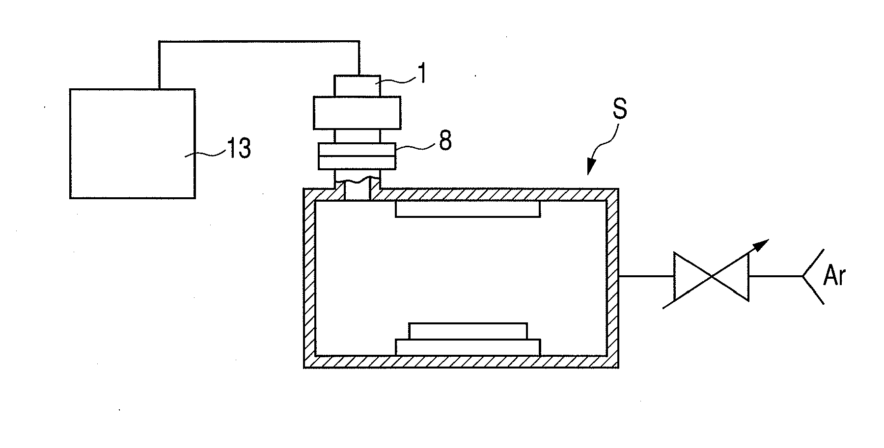
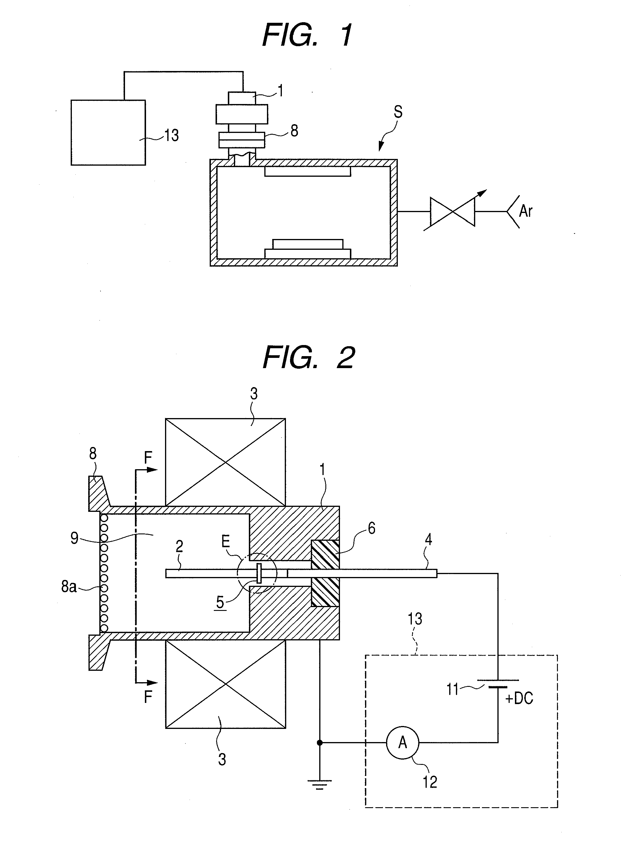
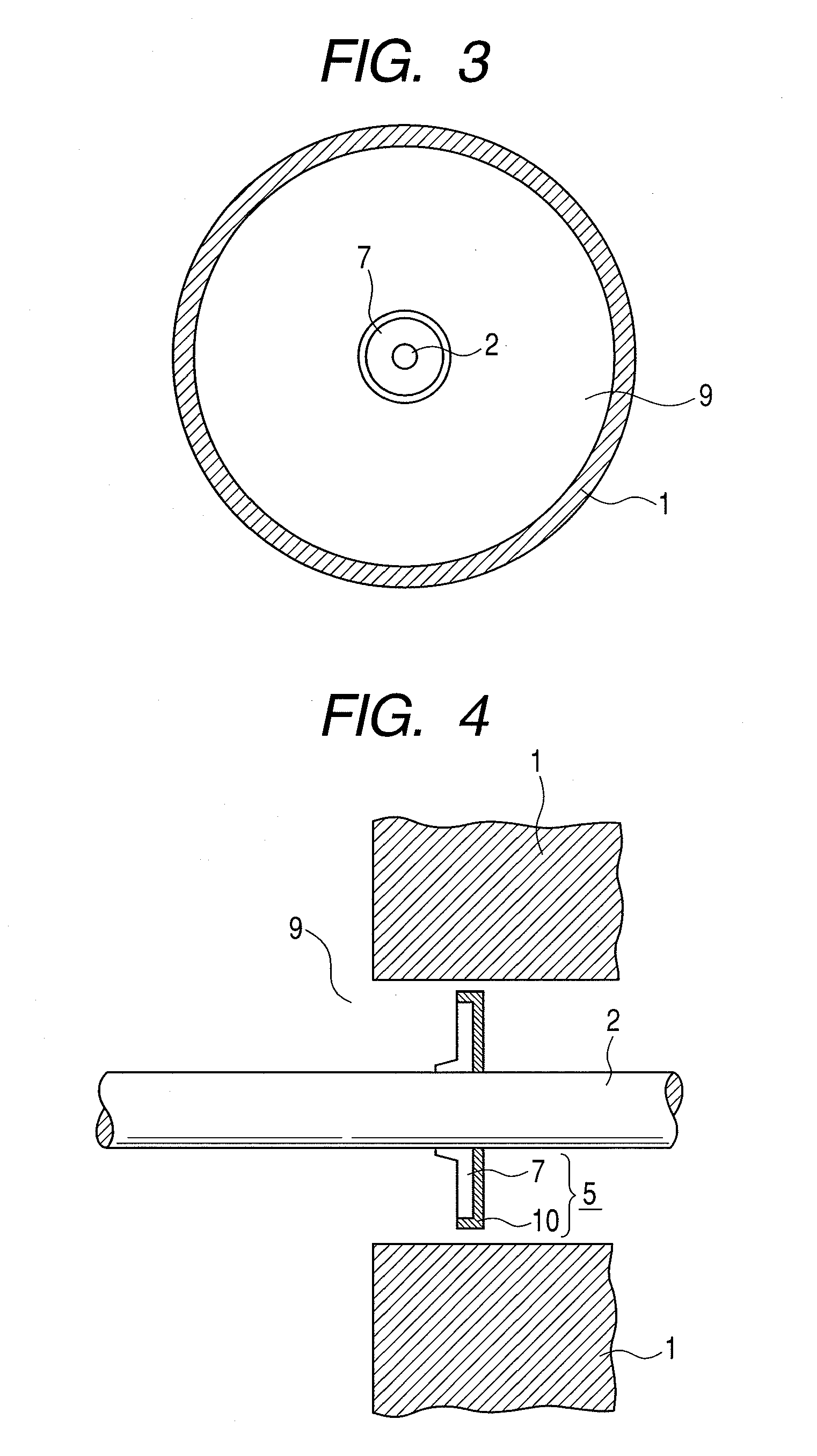
[0042]FIGS. 1 to 4 are drawings for illustrating a vacuum processing apparatus and a cold cathode ionization vacuum gauge mounted on this vacuum processing apparatus according to a first embodiment of the present invention. FIG. 1 is a cross sectional schematic diagram of a vacuum processing apparatus provided with the cold cathode ionization vacuum gauge according to the invention. FIG. 2 is a transverse cross sectional schematic diagram of the cold cathode ionization vacuum gauge according to the invention. FIG. 3 is a cross sectional schematic diagram taken along the line of F-F of FIG. 2. FIG. 4 is an enlarged diagram illustrating an enlarged E portion of FIG. 2. FIG. 5 is a diagram illustrating an application example of using an auxiliary electrode protection plate (cathode auxiliary electrode protection plate).

[0043]As illustrated in FIG. 1, a cold cathode ionization vacuum gauge is mounted on the wall surface (hatched portion) of a known vacuum container forming a vacuum proc...

embodiment 2

[0061]A second embodiment according to the present invention will be described. In this embodiment, the construction of a discharge starting auxiliary electrode differs from that of FIGS. 3 and 4. The construction of a cold cathode ionization vacuum gauge or a vacuum processing apparatus other than the above-mentioned construction are the same as are FIGS. 1 and 2. FIG. 6A is a plan diagram illustrating a discharge starting auxiliary electrode 25 according to this embodiment. FIG. 6B is a side diagram thereof.

[0062]As illustrated in FIG. 6A, a discharge starting auxiliary electrode plate 27 that forms the discharge starting auxiliary electrode 25 has an opening formed for allowing the rod-like anode 2 to be inserted at the central portion. The elastic support claws 23 for mounting the discharge starting auxiliary electrode plate 27 on anode 2 are provided radially around the inner circumference of this opening. Due to the support claws 23, the insertion pressures on the occasion whe...

embodiment 3

[0065]A third embodiment according to the present invention will be described. In this embodiment, likewise the construction of a discharge starting auxiliary electrode differs from that of FIGS. 3 and 4. The constructions of a cold cathode ionization vacuum gauge or a vacuum processing apparatus other than the above-mentioned construction are the same as those of FIGS. 1 and 2.

[0066]FIG. 7A is a plan diagram illustrating a discharge starting auxiliary electrode 35 according to this embodiment. FIG. 7B is a side diagram thereof. FIG. 7C is a cross sectional diagram thereof. The discharge starting auxiliary electrode 35 according to this embodiment is provided with a discharge starting auxiliary electrode plate 37 having two members, that is, an inner electrode member 38 and an outer electrode member 39 which is fixed to the outer circumferential side of the inner electrode member 38.

[0067]The discharge starting auxiliary electrode plate 37 has the structure that an electrode plate (...


PUM


Abstract

The present invention provides a cold cathode ionization vacuum gauge that can trigger discharge in a short time even in the case of use over a long period of time without needing a complicated apparatus. It has the structure in which a rod-like anode is located in an internal part of a measuring element container (cathode) having a discharge space with one end thereof which is sealed, and a discharge starting auxiliary electrode is mounted on this anode. The discharge starting auxiliary electrode triggers the discharge in a short time by the formation of a carbon nanotube layer on a discharge starting auxiliary electrode plate.

Description

CROSS-REFERENCES TO RELATED APPLICATIONS[0001]This application claims the benefit of priorities from Japanese Patent Application No. 2009-094942 filed on Apr. 9, 2009, Japanese Patent Application No. 2009-109097 filed on Apr. 28, 2009 and Japanese Patent Application No. 2010-047685 filed on Mar. 4, 2010, the entire contents of which are incorporated herein by reference.BACKGROUND OF THE INVENTION[0002]1. Field of the Invention[0003]The present invention relates to a cold cathode ionization vacuum gauge, a vacuum processing apparatus including the cold cathode ionization vacuum gauge and a discharge starting auxiliary electrode. In particular, the present invention relates to a cold cathode ionization vacuum gauge using a discharge starting auxiliary electrode, vacuum processing apparatus including a discharge starting auxiliary electrode, and a discharge starting auxiliary electrode.[0004]2. Description of the Related Art[0005]A cold cathode ionization vacuum gauge triggers gas ioni...

Claims


Application Information

Patent Timeline
IPC IPC(8): G01L21/34
CPCH01J41/06G01L21/34
Inventor KAWASAKI, YOHSUKEKIKUCHI, TOSHIO
Owner CANON ANELVA CORP
Why Eureka
Try Eureka