
Providing feedback in an electronic circuit

a technology of electronic circuits and feedback, applied in the direction of resistance/reactance/impedence, instruments, code conversion, etc., can solve the problems of increasing circuit board area and component manufacturing and testing costs, significant inaccuracy of stored analog voltages, and increasing power consumption when compared to circuit operation. to achieve the effect of improving the accuracy of the output of the electronic circui

Inactive Publication Date: 2010-10-14
NOKIA CORP
View PDF12 Cites 29 Cited by
  • Summary
  • Abstract
  • Description
  • Claims
  • Application Information

AI Technical Summary

Benefits of technology

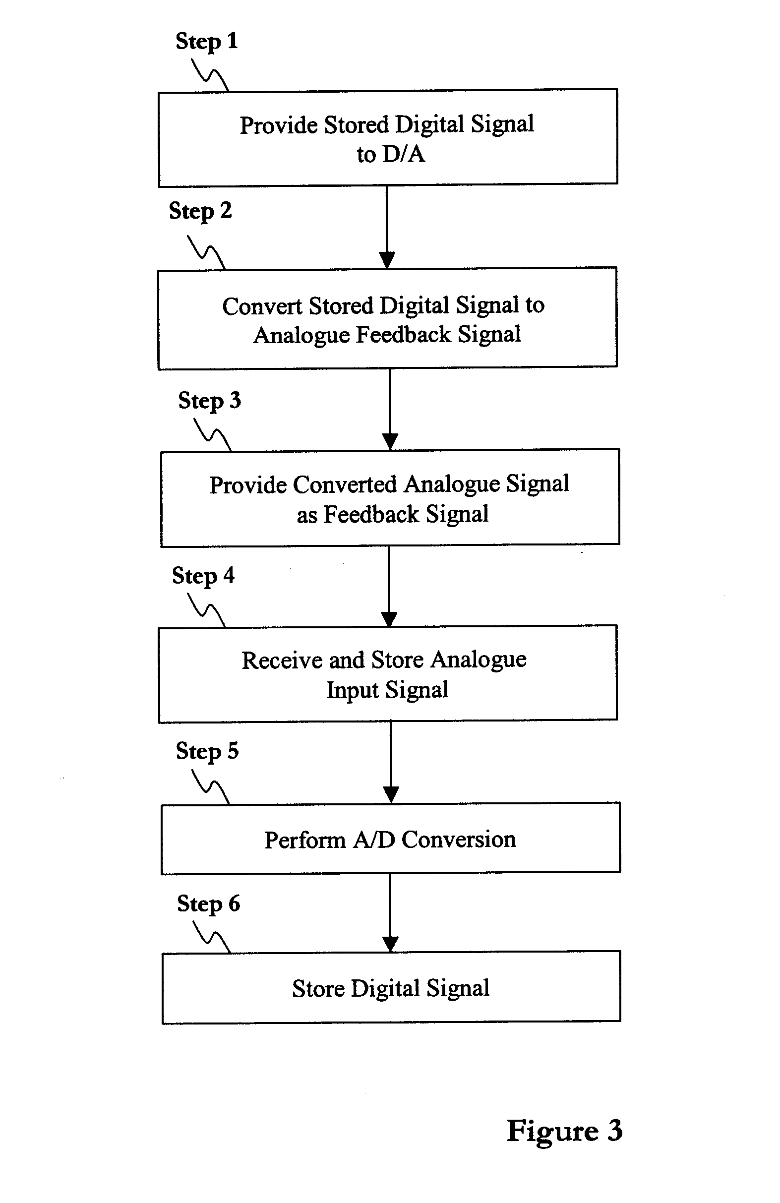
[0007]The present invention therefore provides a method by which feedback can be provided in an electronic circuit without the analogue storage device used in the circuit being required to store the analogue input signal for any longer than is necessary for the analogue signal to be converted into the digital domain. Accordingly, the effects of leakage currents on the signal stored by the analogue storage device can be greatly reduced.
[0017]The method can further comprise providing the digital to analogue converter with predetermined data and wherein the step of using the digital to analogue converter to convert the stored digital signal into an analogue feedback signal comprises using the digital to analogue converter to convert the stored digital signal and the predetermined data into the analogue feedback signal. The predetermined data can, for instance, provide an initial feedback value such that the first output of the electronic circuit is relatively accurate. Alternatively, the predetermined value can, for instance, provide a temperature dependent tuning parameter or other such parameters to improve the accuracy of the output of the electronic circuit.

Problems solved by technology

However, high density CMOS integration technologies result in circuits that exhibit high leakage currents that cause significant inaccuracies in stored analogue voltages, for instance those required to provide feedback in circuits such as the self-balancing bridge.
To avoid such inaccuracies, sampling frequencies are increased, thus limiting the effects of the high leakage currents, but also bringing about an increase in power consumption when compared to circuits operating at lower sampling frequencies.
However, this has the effect of increasing circuit board area and component manufacturing and testing costs.

Method used


Image

  • Providing feedback in an electronic circuit
  • Providing feedback in an electronic circuit
  • Providing feedback in an electronic circuit

Examples


Embodiment Construction

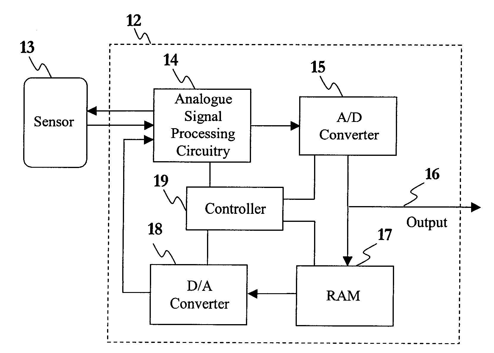
[0042]Referring to FIG. 2, a schematic illustration of an electronic circuit 12 according to the present invention is provided, in this example the front-end circuitry for an analogue sensor 13. The circuitry 12 is, in the present example, implemented in a mobile telephone, on a single chip using 130 nm complimentary metal-oxide-semiconductor (CMOS) integration technology.

[0043]The front-end circuitry 12 includes analogue signal processing circuitry 14 connected to the output of the sensor 13. In the present example, the analogue signal processing circuitry 14 includes an amplifier arranged to amplify the analogue input signal received from the sensor 13, and an analogue storage device to store the input signal. The analogue signal processing circuitry 14 is also configured, in the present example, to adjust the test voltages used in the analogue sensor 13 when taking measurements. However, alternative configurations of the analogue signal processing circuitry 14 can be used, as may...


PUM


Abstract

The invention relates to an electronic circuit and a method capable of providing feedback in the electronic circuit, such that the effect of leakage currents in the circuit are minimised. The method includes the steps of storing an analogue input signal using an analogue storage device, converting the stored analogue input signal into a digital signal and storing the digital signal, converting the stored digital signal into an analogue feedback signal, and providing feedback in the electronic circuit using the analogue feedback signal.

Description

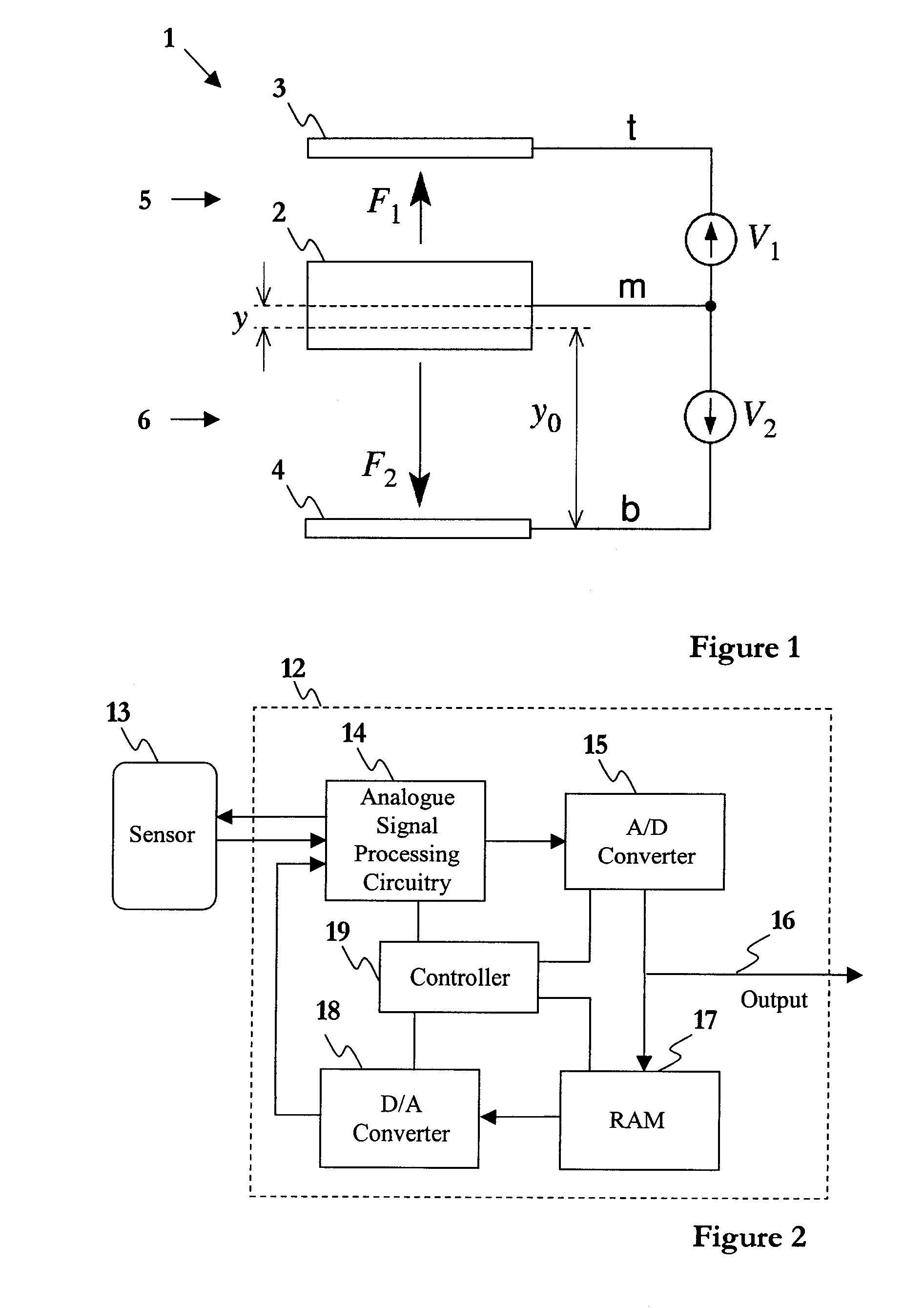
FIELD OF THE INVENTION[0001]The present invention relates to providing feedback in an electronic circuit, particularly but not exclusively to a mixed-mode self-balancing bridge for a capacitive acceleration sensor.BACKGROUND OF THE INVENTION[0002]Referring to FIG. 1, a capacitive accelerometer 1, also referred to as a capacitive acceleration sensor, has a moveable mass 2 arranged between first and second electrodes 3, 4. The arrangement results in first and second capacitors 5, 6 being formed between each respective electrode 3, 4 and the moveable mass 2. Any acceleration applied to the accelerometer 1 will cause a force on the mass 2, which has the effect of changing the plate separation distances of the first and second capacitors 5, 6, which will cause a change in their respective capacitances. Measuring the charge stored by the capacitors 5, 6 provides an indication of the acceleration applied to the accelerometer 1.[0003]In order to take a measurement, a test voltage V1, V2 is ...

Claims


Application Information

Patent Timeline
IPC IPC(8): G01R27/26H03M1/00
CPCG01P15/131G01P15/125
Inventor KOLI, KIMMOSAVOLAINEN, JARIRAKKOLA, JUHA
Owner NOKIA CORP
Learn More