Time synchronization method in wireless sensor network

a wireless sensor and time synchronization technology, applied in the direction of synchronisation arrangement, network topologies, electrical appliances, etc., can solve the problems of not being able to efficiently adjust to a dynamic change in the topology, not being able to use the linear regression method used in the rbs in order to correct clock skew, and not being able to achieve fault tolerance and scalability. good, reduce overhead and conversion time, and reduce the number of times packets are exchang

Active Publication Date: 2010-10-14
ELECTRONICS & TELECOMM RES INST
View PDF3 Cites 22 Cited by
  • Summary
  • Abstract
  • Description
  • Claims
  • Application Information

AI Technical Summary

Benefits of technology

[0017]According to the embodiments of the present invention, there is provided a method of determining a captured node on a wireless sensor network. Therefore, it is possible to provide a time synchronization method that can prevent a Byzantine failure due to a node capture attack.
[0018]A reference node broadcasts a sync reference packet two times and reduces the number of times when packets are exchanged between neighbor nodes. Therefore, it is possible to reduce overhead and...

Problems solved by technology

The TPSN provides much better performance than that of the RBS in a multi-hop environment, but is disadvantageous in that it is not possible to use a linear regression method that is used in the RBS in order to correct clock skew.
Further, the TPSN cannot efficiently adjust to a dynamic change in a topology, and is not good in terms of scalability and a fault-tolerant system.
However, the error elements that have been analyzed in the FTSP become different whenever an applied system is changed.
These features affect accuracy of synchronization, which makes it difficult to generally apply the FTSP.
Meanwhile, the time synchronization methods according to the related art have a drawback in security.
It is almost impossible to prevent the node capture attack and it is difficult...

Method used


Image

  • Time synchronization method in wireless sensor network
  • Time synchronization method in wireless sensor network
  • Time synchronization method in wireless sensor network

Examples


Embodiment Construction

[0026]In the following detailed description, only certain exemplary embodiments of the present invention have been shown and described, simply by way of illustration. As those skilled in the art would realize, the described embodiments may be modified in various different ways, all without departing from the spirit or scope of the present invention. Accordingly, the drawings and description are to be regarded as illustrative in nature and not restrictive. Like reference numerals designate like elements throughout the specification.

[0027]It will be understood that the terms “comprises” and / or “comprising,” when used in this specification, specify the presence of stated features, integers, steps, operations, elements, and / or components, but do not preclude the presence or addition of one or more other features, integers, steps, operations, elements, components, and / or groups thereof.

[0028]Hereinafter, a time synchronization method in a wireless sensor network according to an exemplary...


PUM


Abstract

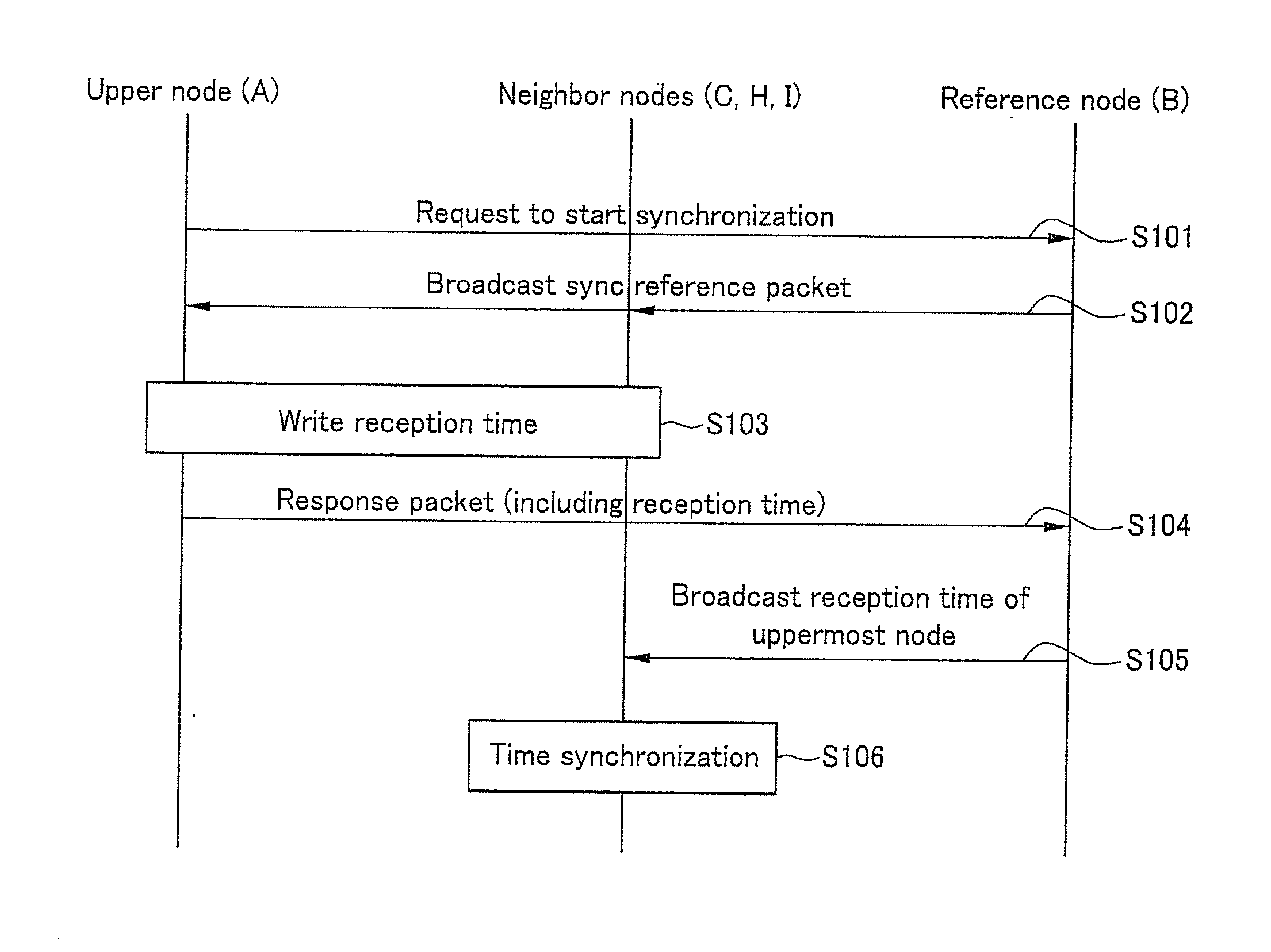
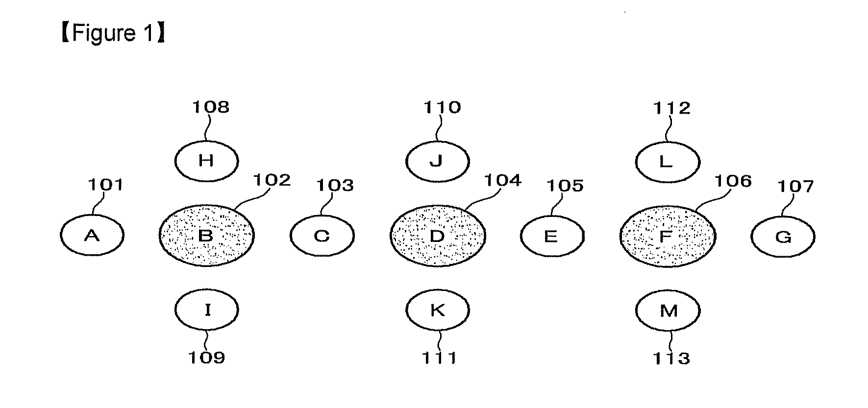
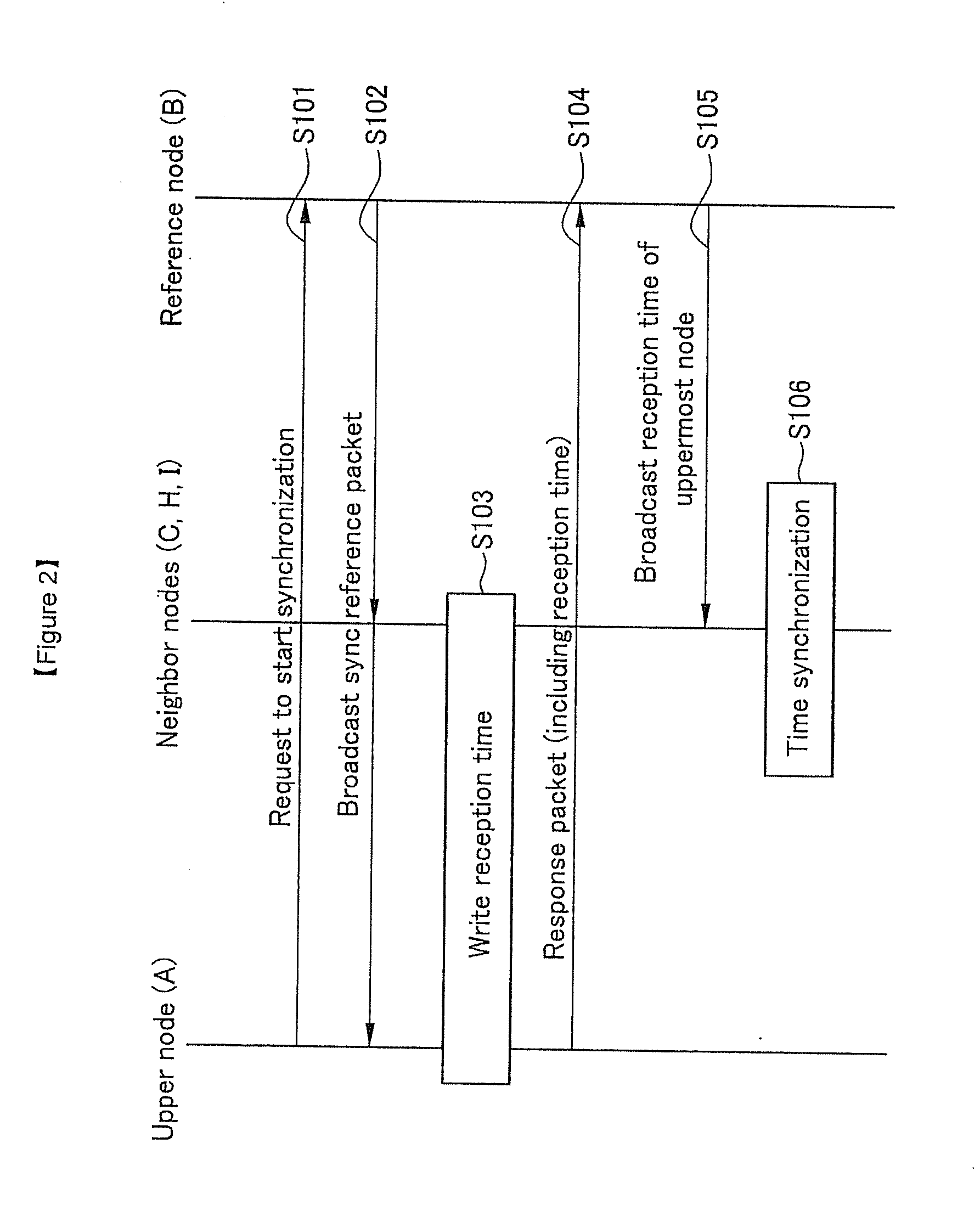
The present invention relates to a time synchronization method in a wireless sensor network. In the present invention, if an upper node requests a lower reference node to start time synchronization, the lower reference node broadcasts a first sync reference packet. The upper node receives the first sync reference packet and transmits the first sync reference packet reception time to the lower reference node. The lower reference node broadcasts the first sync reference packet reception time, such that the other nodes perform time synchronization on the basis of the first sync reference packet reception time. Meanwhile, the lower reference node estimates the first sync reference packet reception time of the upper node to calculate the reception estimation time, and transmits the reception estimation time to a determination node that is two hops anterior to the lower reference node. Therefore, the determination node compares the reception time received from the upper node and the reception estimation time received from the lower reference node and determines whether a capture attack on the upper node has occurred.

Description

TECHNICAL FIELD[0001]The present invention relates to a time synchronization method in a wireless sensor network.[0002]The present invention was supported by the IT R&D program of MIC / IITA [2006-S-024-02, Development of Telematics Application Service Technology based on USN Infrastructure].BACKGROUND ART[0003]In a wireless sensor network, communication between nodes is generally performed using a broadcasting method.[0004]In the related art, reference broadcast synchronization (RBS) has been suggested as a time synchronization method in which energy efficiency is improved on the basis of characteristics of a wireless sensor network and error elements occurring at the time of applying a time difference calculation method through a timestamp message exchange are considered. In the RBS, nodes receive reference signals that are broadcast on a wireless sensor network, and use arrival points of time of the reference signals at the time of time comparison with other nodes to perform time s...

Claims


Application Information

Patent Timeline
IPC IPC(8): H04W56/00
CPCH04J3/0667H04W84/18H04W12/12H04J3/0673H04W12/61H04W56/00
Inventor KIM, KYEONG TAEJANG, BYUNG TAECHOI, JEONG DANKIM, DO HYUNYOO, JAE JUNSUNG, KYUNG BOKKIM, JUNG SOOKLIM, JAE HANJANG, JEONG AH
Owner ELECTRONICS & TELECOMM RES INST
Why Eureka
Try Eureka