Water jet propulsion watercraft

a watercraft and water jet technology, applied in marine propulsion, machine/engine, vessel construction, etc., can solve the problems of high combustion efficiency, low amount of fuel and oxygen in the exhaust, and inability to easily ignite a catalyst unit, so as to prevent the backflow of water into the catalyst unit and the retention of water in the catalyst unit.

Active Publication Date: 2010-10-14
YAMAHA MOTOR CO LTD
View PDF4 Cites 4 Cited by
  • Summary
  • Abstract
  • Description
  • Claims
  • Application Information

AI Technical Summary

Benefits of technology

[0026]Preferably, the first exhaust pipe is coupled to the catalyst unit upon extending horizontally rearward from the side of the engine. By this arrangement, the exhaust gas path length between the engine and the catalyst unit can be made short and, at the same time, the formation or accumulation of condensed water in the first exhaust pipe can be prevented.
[0027]Preferably, the water jet propulsion watercraft further includes a second exhaust pipe connected to the catalyst unit and arranged to guide the exhaust gas that has been discharged from the engine and has passed through the first exhaust pipe and the catalyst unit, and the second exhaust pipe does not include a portion that inclines upward toward the downstream side. By this arrangement, water that is formed by the reaction of the components (for example, HC, CO, NOx, etc.) contained in the exhaust gas in the catalyst unit can be made to flow out to the downstream side of the second exhaust pipe. Retention of water in the catalyst unit can thereby be prevented.
[0028]Preferably, in this case, the second exhaust pipe is arranged to incline downward toward the downstream side. By this arrangement, the water that forms or accumulates in the catalyst unit can be made to flow out toward the downstream side more smoothly from the second exhaust pipe. Back flow of the water into the catalyst unit can thereby be prevented.
[0029]Preferably, the water jet propulsion watercraft further includes a second exhaust pipe connected to the catalyst unit an...

Problems solved by technology

That is, it was discovered that although the exhaust apparatus according to the prior art described above is well applied to a two-stroke cycle engine, challenges arise in application to a water jet propulsion watercraft that includes a four-stroke cycle engine, which is higher in combustion efficiency.
Also, in a four-stroke cycle engine, the amounts of fuel and oxygen contained in the exhaust are low.
Combustion ...

Method used


Image

  • Water jet propulsion watercraft
  • Water jet propulsion watercraft
  • Water jet propulsion watercraft

Examples


first preferred embodiment

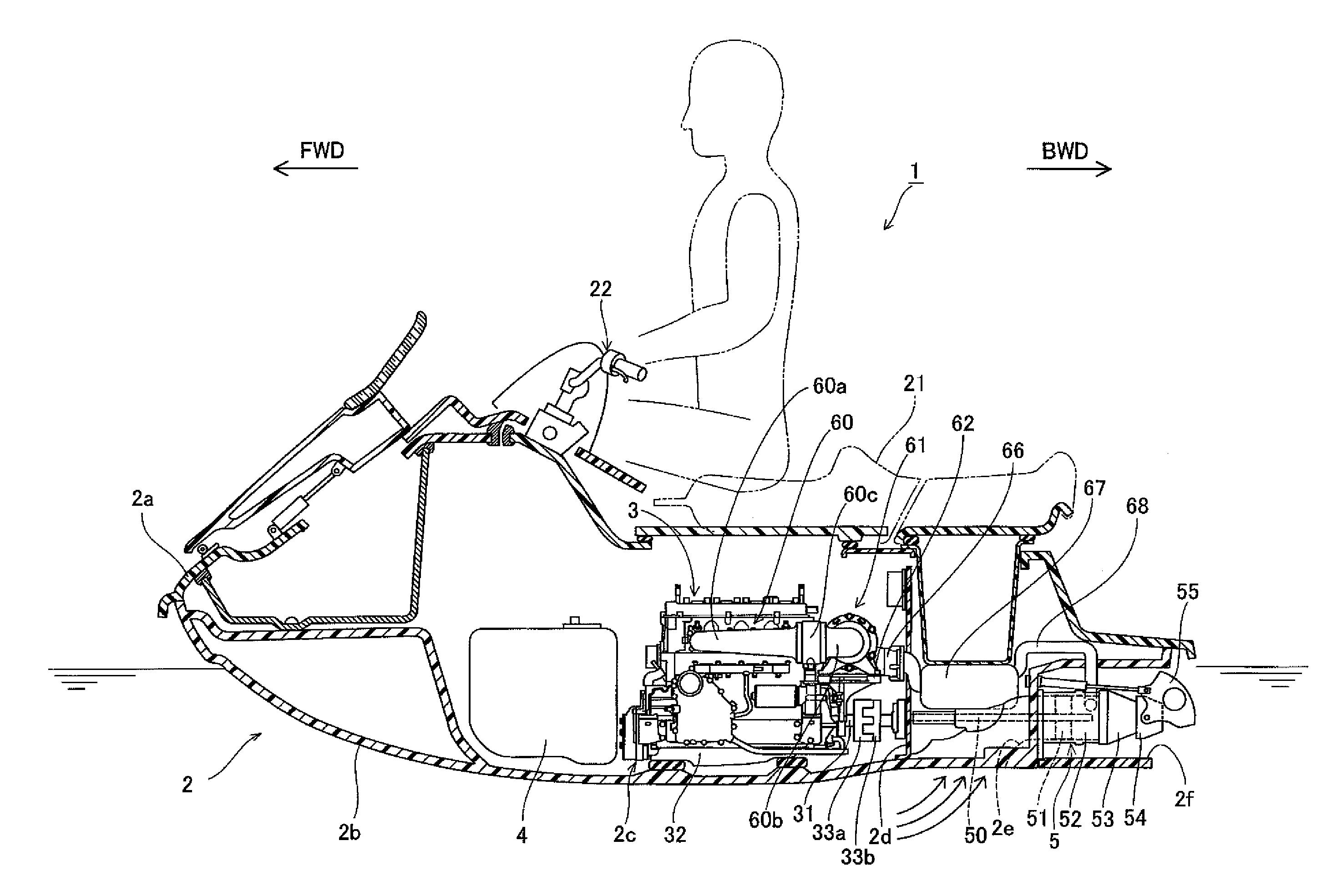
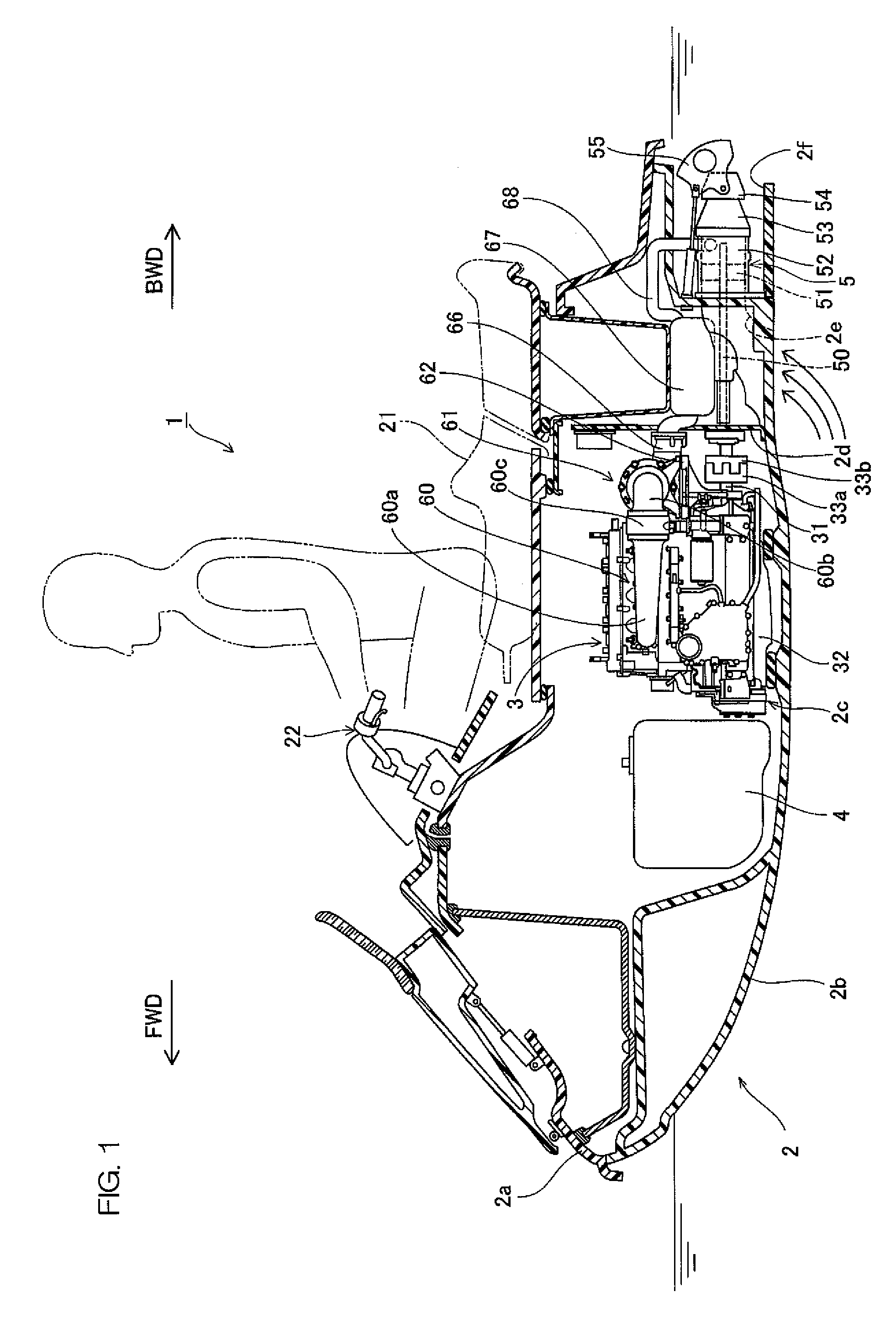
[0048]An arrangement of a water jet propulsion watercraft according to a first preferred embodiment of the present invention shall now be explained with reference to FIG. 1 to FIG. 9. In the figures, FWD indicates a forward drive direction of the watercraft, and BWD indicates a reverse drive direction of the watercraft.

[0049]FIG. 1 is a sectional view of an overall arrangement of the water jet propulsion watercraft according to the first preferred embodiment of the present invention. The water jet propulsion watercraft 1 includes a hull 2, an engine 3 housed in an inside of the hull 2, a jet propulsion unit 5 arranged to be driven by the engine 3, and a catalyst unit 61 arranged to purify an exhaust gas of the engine 3. The hull 2 includes a deck 2a and a hull body 2b. A sealed engine room 2c, arranged to house the engine 3, a fuel tank 4, etc., is provided in the inside of the hull 2. A partition plate 2d, extending vertically upward from a bottom portion of the hull body 2b, is pr...

second preferred embodiment

[0094]A structure of a water jet propulsion watercraft according to a second preferred embodiment of the present invention shall now be described with reference to FIG. 10 to FIG. 12. In the second preferred embodiment, an exhaust manifold unit 160 is arranged to extend downward from a side of an engine 103 and then curve toward the upper rear.

[0095]FIG. 10 is a side view for explaining a structure in a vicinity of the engine and a catalyst unit of the water jet propulsion watercraft according to the second preferred embodiment of the present invention, and FIG. 11 is a rear view thereof. FIG. 12 is a sectional view for explaining the structure in the vicinity of the catalyst unit.

[0096]As shown in FIG. 10, the exhaust manifold unit 160, which leads out the exhaust gas discharged from the engine 103, is attached to the side of the engine 103. The exhaust manifold unit 160 is an example of the “first exhaust pipe” according to a preferred embodiment of the present invention. The exha...


PUM


Abstract

A water jet propulsion watercraft includes a hull having a sealed engine room, an engine installed in the engine room, a jet propulsion unit arranged to be driven by the engine so as to suck in water from around the hull and jet the water, a saddle type seat disposed above the engine room, a first exhaust pipe, an exhaust pipe cooling unit, and a catalyst unit. The first exhaust pipe is attached to a side of the engine inside the engine room, extends rearward from the side of the engine, and is arranged to guide exhaust gas discharged from the engine. The exhaust pipe cooling unit is arranged to cool the first exhaust pipe. The catalyst unit is connected to the first exhaust pipe, is disposed inside the engine room so as to oppose a rear surface of the engine, and is arranged to promote reaction of components contained in the exhaust gas.

Description

BACKGROUND OF THE INVENTION[0001]1. Field of the Invention[0002]The present invention relates to a saddle type water jet propulsion watercraft that includes a jet propulsion unit driven by an engine, and particularly relates to a water jet propulsion watercraft that includes a catalyst unit, which promotes reaction of exhaust gas from the engine.[0003]2. Description of the Related Art[0004]An exhaust apparatus of a small-scale marine vessel (water jet propulsion watercraft) according to a prior art is disclosed in U.S. Pat. No. 6,106,344. This exhaust apparatus includes an exhaust passage arranged to extend forward from one side of a two-stroke cycle engine and then curve from the front of the engine to the other side of the engine. The exhaust apparatus further includes a catalyst connected to the exhaust passage at a rear portion of the other side of the engine. The exhaust passage is thus disposed so as to surround both sides and the front of the engine, and the catalyst is conne...

Claims


Application Information

Patent Timeline
IPC IPC(8): F01N3/10B63H21/32
CPCB63H21/32F01N3/043F01N13/12B63H21/383F01N13/1805Y02T10/20B63H11/02F01N13/141Y02T10/12
Inventor OZAWA, SHIGEYUKI
Owner YAMAHA MOTOR CO LTD
Why Eureka
Try Eureka