Heating and cooling unit, and heating and cooling apparatus

a heating and cooling unit and heating and cooling technology, applied in the field of heating and cooling units and heating and cooling apparatuses, can solve the problems of low air conditioning efficiency of the heating and cooling apparatus described above, uneven temperature at the room inside, and low efficiency of the heating and cooling apparatus which uses radiation cooling or radiation heating, so as to reduce draft, reduce heat loss, and uniform temperature distribution

Active Publication Date: 2010-10-21
KIMURA KOHKI CO LTD
View PDF10 Cites 47 Cited by
  • Summary
  • Abstract
  • Description
  • Claims
  • Application Information

AI Technical Summary

Benefits of technology

[0010]The present invention has been made in view of such a situation, and an object thereof is to provide a heating and cooling unit and a heating and cooling apparatus in which since supplying mixed air which is obtained by mixing feed air to be fed and circulated air from the room inside, to the room inside in a laminar manner, and emitting heat obtaining from the mixed air, to the room inside so as to carry out an air conditioning of the room inside, it becomes to possible to get high efficiency and high power, to reduce a space unsuitable for air conditioning than air conditioning by the conventional radiation panel employing only heat emission, to prevent a draft and temperature unevenness, to expand the range of usage of the apparatus, and to avoid the need of a measures against dew condensation.
[0134]With the heating and cooling apparatus according to the present invention, since it is possible to sufficiently secure the vaporization and absorption distance in the humidification of the feed air, by the air blowing path, it is possible to enhance a saturation effect even in the compact air conditioning apparatus such as the fan coil and to enhance comfort by extending the temperature control range.

Problems solved by technology

On the other hand, a heating and cooling apparatus such as a multi air conditioner or a fan coil unit described above has a problem that the wind velocity of cold air or warm air from an indoor equipment installed at the room inside is too high, and causes the user of the room inside to feel a draft and tends to cause temperature unevenness at the room inside.
Moreover, the air conditioning efficiency of the heating and cooling apparatus described above, which uses radiation cooling or radiation heating, is low since only low heat or high heat due to radiation cooling or radiation heating is employed therein, and the range of use of the heating and cooling apparatus is limited.
For example, it is not appropriate to use the heating and cooling apparatus in a place having poor thermal insulation properties, a place having a large thermal load, or a place having much air flowing into and out thereof.
Moreover, there is another problem that it is necessary to provide measures against dew condensation or the like separately, which causes cost increase.
However, the ceiling heating-cooling radiation panel of the Patent Literature 1 cannot resolve the above problems.
Moreover, since the protrusions come into contact with the mixed air at this time, heat is obtained from the mixed air and transferred not only by the flow dividing fins but also by the protrusions more uniformly over the entire area of the heat storage radiation member, and occurrence of temperature unevenness in radiation heating to the room inside and in supply of mixed air is inhibited.
Accordingly, the space unsuitable for the air conditioning is less than the air conditioning by the conventional radiation panel employing only heat emission, and the range of use of the apparatus is wide.

Method used


Image

  • Heating and cooling unit, and heating and cooling apparatus
  • Heating and cooling unit, and heating and cooling apparatus
  • Heating and cooling unit, and heating and cooling apparatus

Examples


embodiment 1

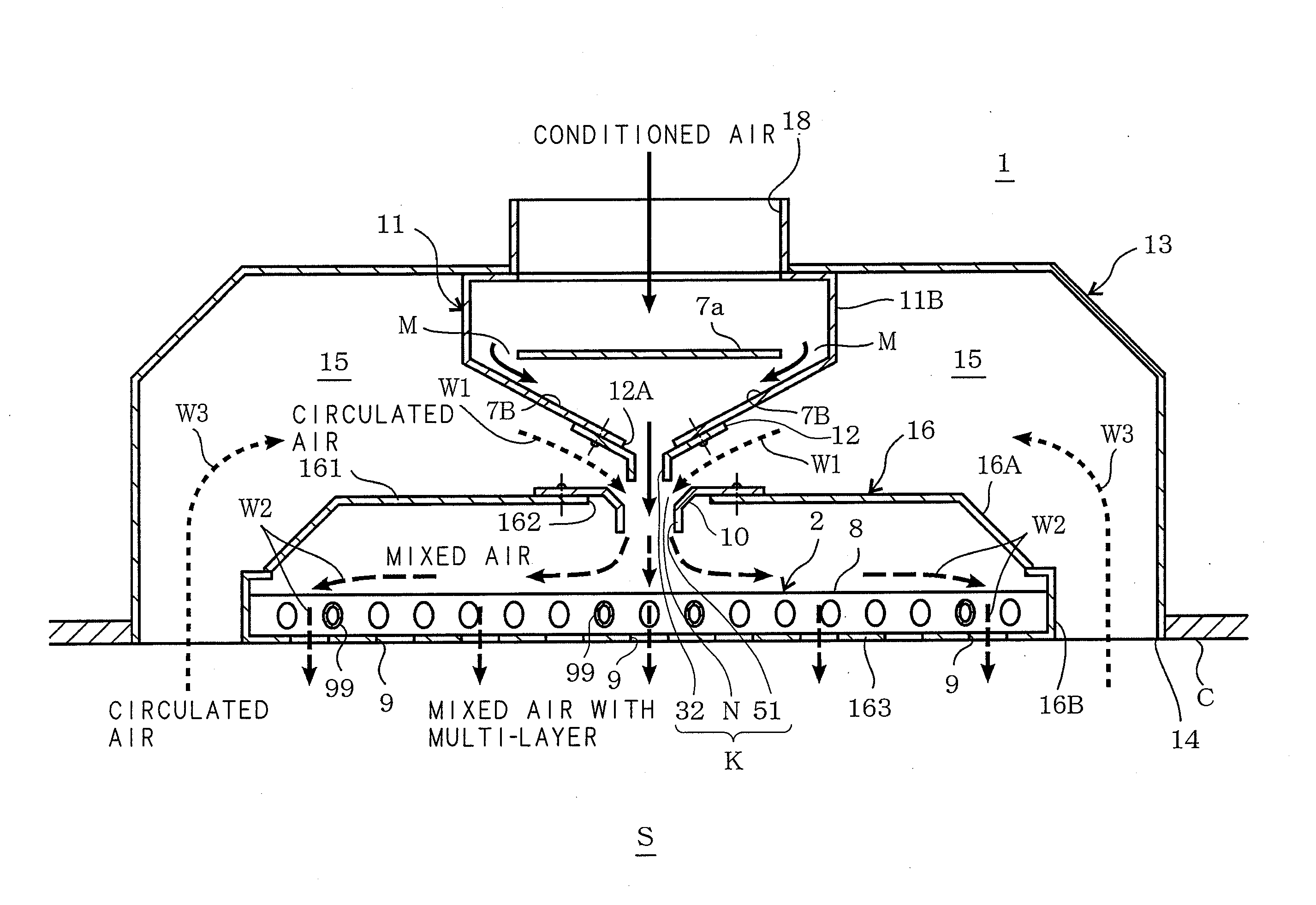
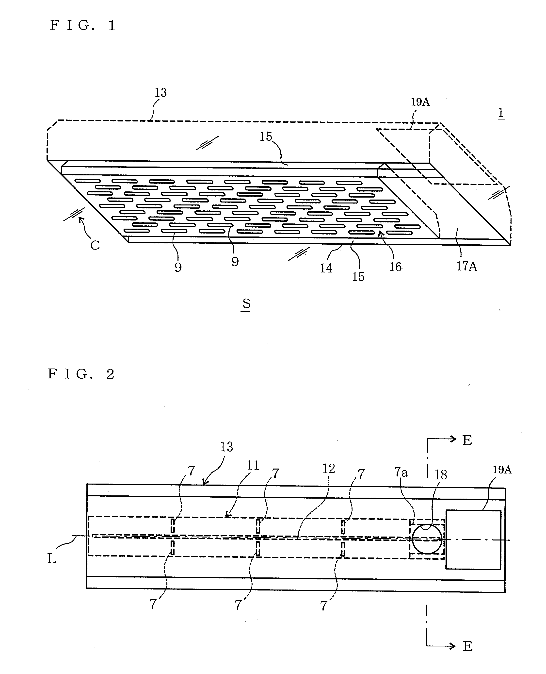
[0165]FIG. 1 is a perspective view of a heating and cooling unit 1 of the present invention viewed from the bottom face side thereof, and FIG. 2 is a plan view of the heating and cooling unit 1 of the present invention. The heating and cooling unit 1 of the present invention comprises: a hood (box member) 13; an adjustment case 11 for receiving air-conditioned air from the air conditioning apparatus and adjusting the flow of the air-conditioned air; and a mixer case 16 for mixing air-conditioned air delivered from the adjustment case 11 with circulated air from the room inside and delivering the air to the room inside.

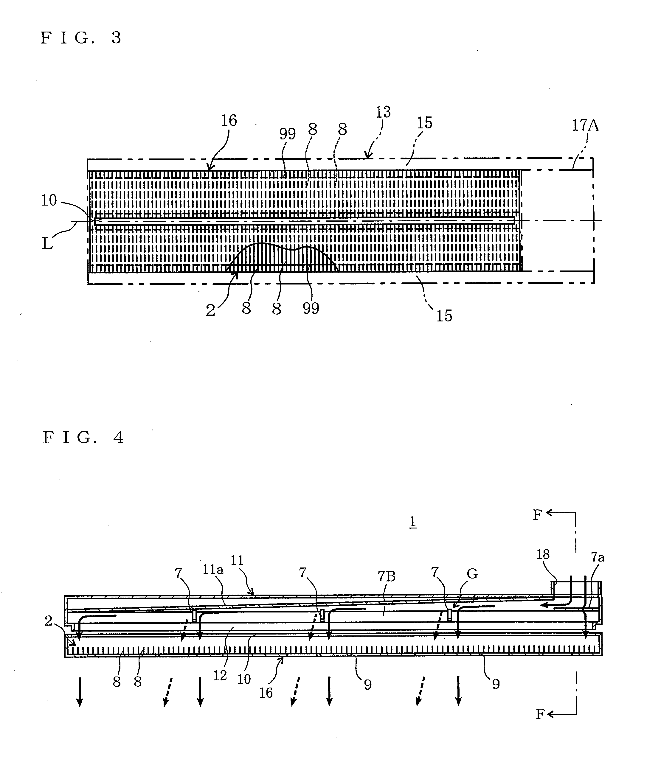
[0166]FIG. 3 is a plan view of the heating and cooling unit 1 of the present invention wherein a part of an upper face of the mixer case 16 thereof is cut away, FIG. 4 is a sectional side view of the adjustment case 11 and the mixer case 16 of the heating and cooling unit 1 of the present invention, FIG. 5 is an overall sectional view viewed from the E direction of FIG...

embodiment 2

[0206]FIG. 9 is a sectional view of a main part of a heating and cooling unit 1 of Embodiment 2 of the Present Invention. In the heating and cooling unit 1 of Embodiment 2, a lighting system R for lighting room inside S is provided at an edge part of a lower opening part 14 of a hood 13.

[0207]The size of the other face 163 of a mounting part 16B is smaller than the size of the lower opening part 14 of the hood 13, and a clearance (passage clearance) 141 is formed between the lower opening part 14 of the hood 13 and the other face 163 of the mounting part 16B when the heating and cooling unit 1 is installed. Circulated air from the room inside S passes the clearance 141 and is suctioned into a circulated air path 15.

[0208]The lighting system R is provided at the clearance 141 in a proper manner. The lighting system R is provided so as not to obstruct circulated air passing the clearance 141, so that circulated air can pass freely. That is to say, the lighting system R is exposed to c...

embodiment 3

[0211]FIG. 10 is a sectional view of a main part of a heat storage radiation flow divider 2 of Embodiment 3 of the present invention wherein a part thereof is omitted, and FIG. 11 is a sectional view of a main part of a mixer case 16 and a heat storage radiation flow divider 2 of Embodiment 3 viewed from the J direction of FIG. 10.

[0212]A heating and cooling unit 1 of Embodiment 3 comprises short tubular protrusions 98, 98, 98, . . . 98 formed to protrude from one face of each heat transfer plate 8.

[0213]The protrusions 98, 98, 98, . . . 98 are juxtaposed at one face of each heat transfer plate 8 at a proper interval along the longitudinal direction of the heat transfer plate 8. More particularly, apertures 9 are juxtaposed below the respective protrusions 98 at a predetermined interval as illustrated in FIG. 10. The protrusions 98 have an elliptical cross section and are provided in a manner such that the major axis direction of the ellipse is oriented to the vertical direction. Mo...


PUM


Abstract

In an induction emission air conditioning apparatus installed in a ceiling, it is provided within a casing with a heat exchanger through which a feed air introduced from an outdoor side passes, a fan passing the feed air through the air conditioning heat exchanger, and a heating and cooling unit 1 for blowing a mixed air obtained by inducing and suctioning the air in the room inside by using the feed air passing through the heat exchanger so as to mix with the feed air, into the room inside in a laminar manner, and emitting the heat of the mixed air to the room inside, integrally.

Description

CROSS-REFERENCE TO RELATED APPLICATION[0001](US only) This Nonprovisional application claims priority under 35 U.S.C. §119(a) on Patent Application No. 2009-096725 filed in Japan on Apr. 13, 2009, Patent Application No. 2009-138717 filed in Japan on Jun. 9, 2009, Patent Application No. 2009-167201 filed in Japan on Jul. 15, 2009, Patent Application No. 2009-286684 filed in Japan on Dec. 17, 2009, Patent Application No. 2010-016962 filed in Japan on Jan. 28, 2010, the entire contents of which are hereby incorporated by reference.BACKGROUND[0002]1. Technical Field[0003]The present invention relates to a heating and cooling unit and a heating and cooling apparatus for adjusting the temperature of feed air to be fed and supplying air to the room inside.[0004]2. Description of Related Art[0005]A heating and cooling apparatus for carrying out comfortable heating and cooling by, for example, burying a heating and cooling unit provided with a radiation panel, in which a plurality of pipes f...

Claims


Application Information

Patent Timeline
Patent Type & Authority Applications(United States)
IPC IPC(8): F24F7/007F28F7/00F28F13/12F24F3/14F24F1/00F24F1/01
CPCF24F1/01F24F5/0089F24F2221/14F24F2001/0062F24F5/0092F24F13/078F24F1/00075
Inventor KIMURA, KEIICHIMORITA, MITSUOKASAHARA, KAZUYUKIURANO, KATSUHIRO
Owner KIMURA KOHKI CO LTD
Why Eureka
Try Eureka