Safety cabin

a cabin and safety technology, applied in the field of cabin systems, can solve the problems of difficult repair, injuring passengers in the cabin, and conventional cabin concepts do not provide any help in this context, so as to improve mechanical strength and quality, reduce components and installation costs, and facilitate installation more quickly

Inactive Publication Date: 2010-10-21
AIRBUS OPERATIONS GMBH
View PDF17 Cites 10 Cited by
  • Summary
  • Abstract
  • Description
  • Claims
  • Application Information

AI Technical Summary

Benefits of technology

[0007]By means of such a cabin system according to the invention a particularly safe cabin can be constructed that comprises characteristics of a safety cell. All the components used can be combined and can be tensioned among one another so that they conform to the contour of the fuselage and affix themselves to the fuselage without the need to provide a multitude of connection elements and openings In particular in the case of aircraft fuselages made from fibre composite materials this results in a continuous and advantageous fibre alignment of structural elements, which in turn results in improved mechanical strength and quality and also ensures that splintering or fragmenting material cannot enter the cabin through a safe cabin wall that is structurally self-contained even if the fuselage is damaged. In addition, costs of components and installation are reduced because installation can be carried out more quickly because there are no longer any separate connection elements. Moreover, the cabin that comprises such lining components according to the invention is of a particularly low-maintenance character because no attachment elements or tools are required for its installation or deinstallation. In an ideal case the attachment principle is invisible to passengers, and no component requires deinstallation of other components.

Problems solved by technology

Conventional cabin concepts do not provide any help in this context, because they are designed to cope with easily controllable metal fuselages.
In the case of damage to the fuselage no foreign objects must enter the cabin, thus potentially injuring passengers in the cabin.
This design is associated with a disadvantage in that a multitude of connection elements need to be affixed within the aircraft fuselage, to which connection elements the panels are fixed.
This is extremely unfavourable in a CFP fuselage, because such connection elements involve very considerable integration expenditure, are difficult to repair, and reduce the mechanical quality of the preferably smooth surfaces of the fuselage.

Method used


Image

  • Safety cabin
  • Safety cabin
  • Safety cabin

Examples


Embodiment Construction

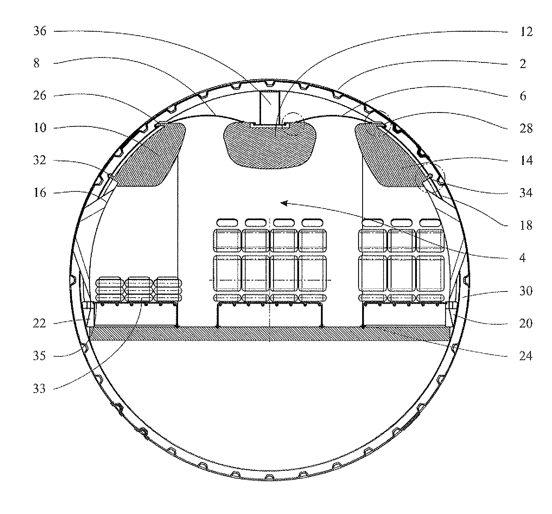
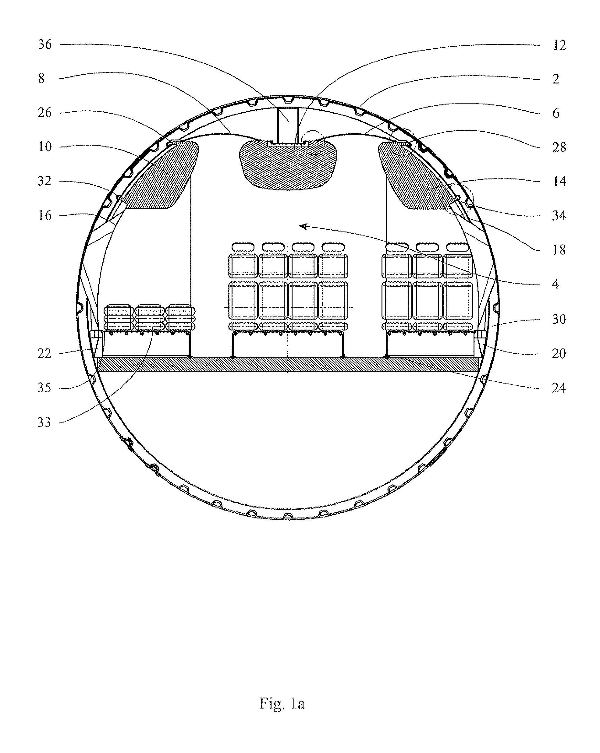
[0016]FIG. 1a shows a cross section of an aircraft fuselage 2 into which a cabin 4 is integrated. The cabin 4 comprises ceiling lining components 6 and 8, overhead bins (also known as hatracks) 10, 12 and 14, lateral lining components 16 and 18, supply ducts 20 and 22, as well as a cabin floor 24. These elements 4 to 24 together define at least one section of a passenger cabin in the form of a closed safety cell.

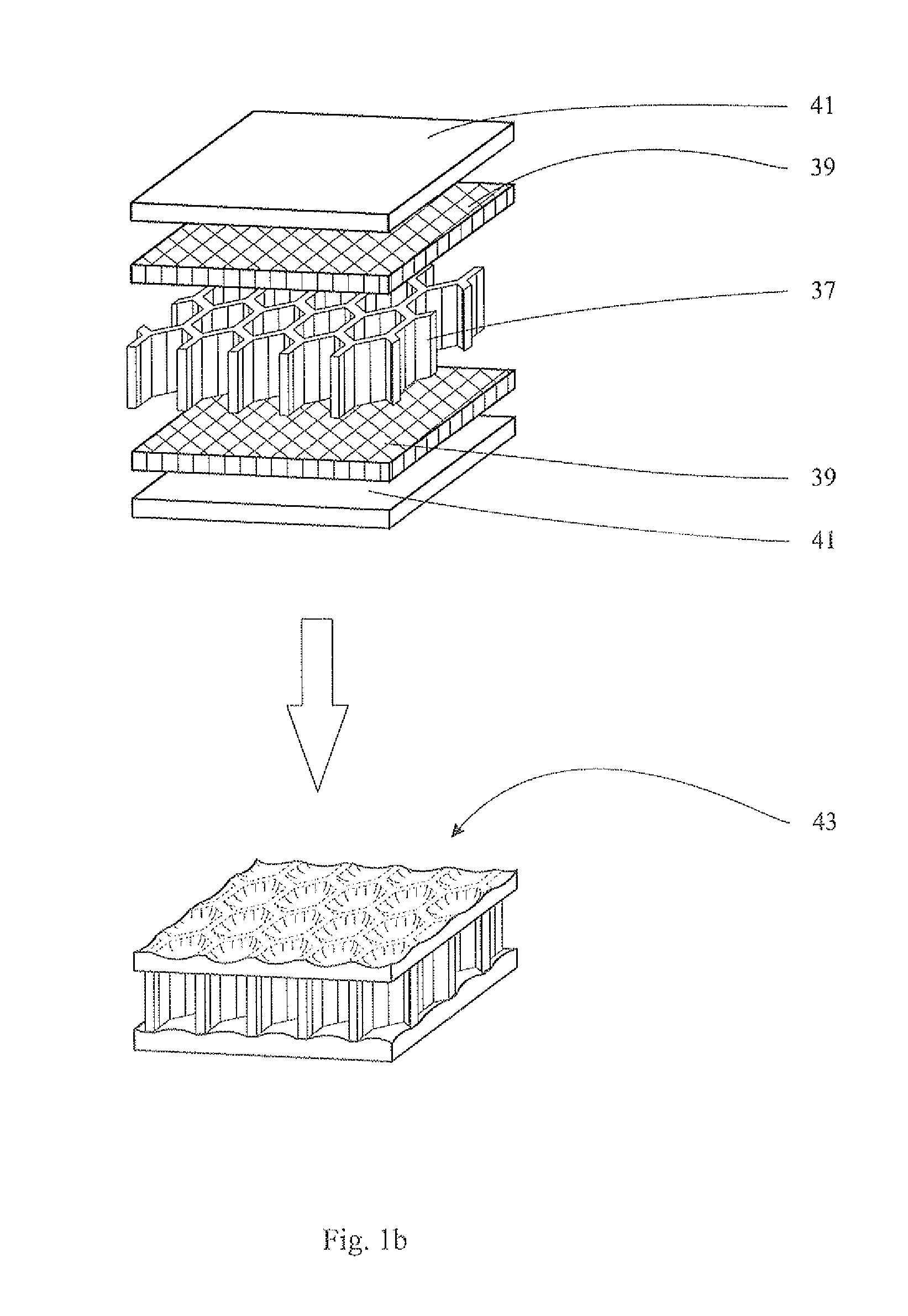
[0017]The above-mentioned components preferably comprise an impact-resistant material, for example glass-fibre reinforced plastic (GFP) or a similar laminate comprising aramid fibres. The strength of the material can be increased by providing additional intermediate layers comprising Kevlar. The material is, in particular, suitable to resist impacts of splinters or fragments of the fuselage material.

[0018]In this diagram the two lateral overhead bins 10 and 14 are each hooked into frame elements 30 by an upper end 26 and 28, and are each detachably locked into place in the f...


PUM


Abstract

The invention relates to a cabin system for an aircraft fuselage, having one or more lining components for interior lining, and optionally one or more cabin equipment components, wherein the lining component can be installed either separately or in combination with a further lining component and/or a cabin equipment component under tension in the aircraft fuselage such that a cabin that is under tension in the circumferential direction and attaches to the aircraft fuselage is defined. In this manner a passenger cabin configured as a closed safety cell is created in a fuselage, which is of particular advantage in an aircraft fuselage made of a fiber composite material because no splinters or the like can penetrate the self-supporting passenger cabin in case of damage to the same.

Description

[0001]The present invention claims priority of the U.S. provisional patent application No. 61 / 008,424, filed on 20 Dec. 2007, and of the German patent application no. 10 2007 061 423.5, filed on 20 Dec. 2007, with the present document referring to their contents.FIELD OF THE INVENTION[0002]The invention relates to a cabin system for an aircraft fuselage, comprising one or several lining components for lining the interior, and optionally comprising one or several cabin equipment components.BACKGROUND TO THE INVENTION[0003]Such cabin systems are well known. Usually in known cabin systems the lining components or all cabin components, respectively, are primarily attached to the external structure of an aircraft, which at present is usually still predominantly made of aluminium. In the development of modern aircraft fuselages comprising fibre composite materials, for example CFP (carbon-fibre reinforced plastic), passenger comfort also requires interior linings whose attachment is plann...

Claims


Application Information

Patent Timeline
Patent Type & Authority Applications(United States)
IPC IPC(8): B64D11/00
CPCB64D11/003B64C1/066
Inventor SCHNEIDER, UWE
Owner AIRBUS OPERATIONS GMBH
Why Eureka
Try Eureka