Short Distance Range Resolution in Pulsed Radar

a pulsed radar and short distance range technology, applied in the field of short distance range pulsed radar systems, can solve the problems of small phase and/or amplitude perturbations at the points in the carrier signal, and achieve the effect of inexpensive amplification

Inactive Publication Date: 2010-10-21
PRECO ELECTRONICS
View PDF7 Cites 37 Cited by
  • Summary
  • Abstract
  • Description
  • Claims
  • Application Information

AI Technical Summary

Benefits of technology

[0018]Very short-range object detection and high-resolution ranging is accomplished in pulsed radar by using a sampling receiver to time-stretch the microwave radar carrier signal within the radar receiver. The resulting audio frequency signal is a replica of the microwave carrier with all characteristics well preserved, but time-stretched. This signal can then be very inexpensively amplified and filtered via conventional audio signal processing hardware and can then be successfully processed in a conventional low-cost microprocessor with audio signal processing capability to look for small to large phase and amplitude features of the carrier waveform. This results in timing detection resolution capability of much less than a single microwave carrier cycle (i.e., picoseconds timing resolution is possible).

Problems solved by technology

Reflections from close objects that enter the receiver while the radar is still transmitting a pulse, and reflections from closely spaced objects at distances that overlap each other in the receiver result in small phase and / or amplitude perturbations at the points in the carrier signal where overlapping begins.

Method used


Image

  • Short Distance Range Resolution in Pulsed Radar
  • Short Distance Range Resolution in Pulsed Radar
  • Short Distance Range Resolution in Pulsed Radar

Examples


Embodiment Construction

[0030]While the focus of the invention description herein is on very close object detection and ranging practice, the described invention can be equally well used to realize enhanced ranging resolution for longer distance objects as well as detection of multiple object reflections overlapping in the receiver.

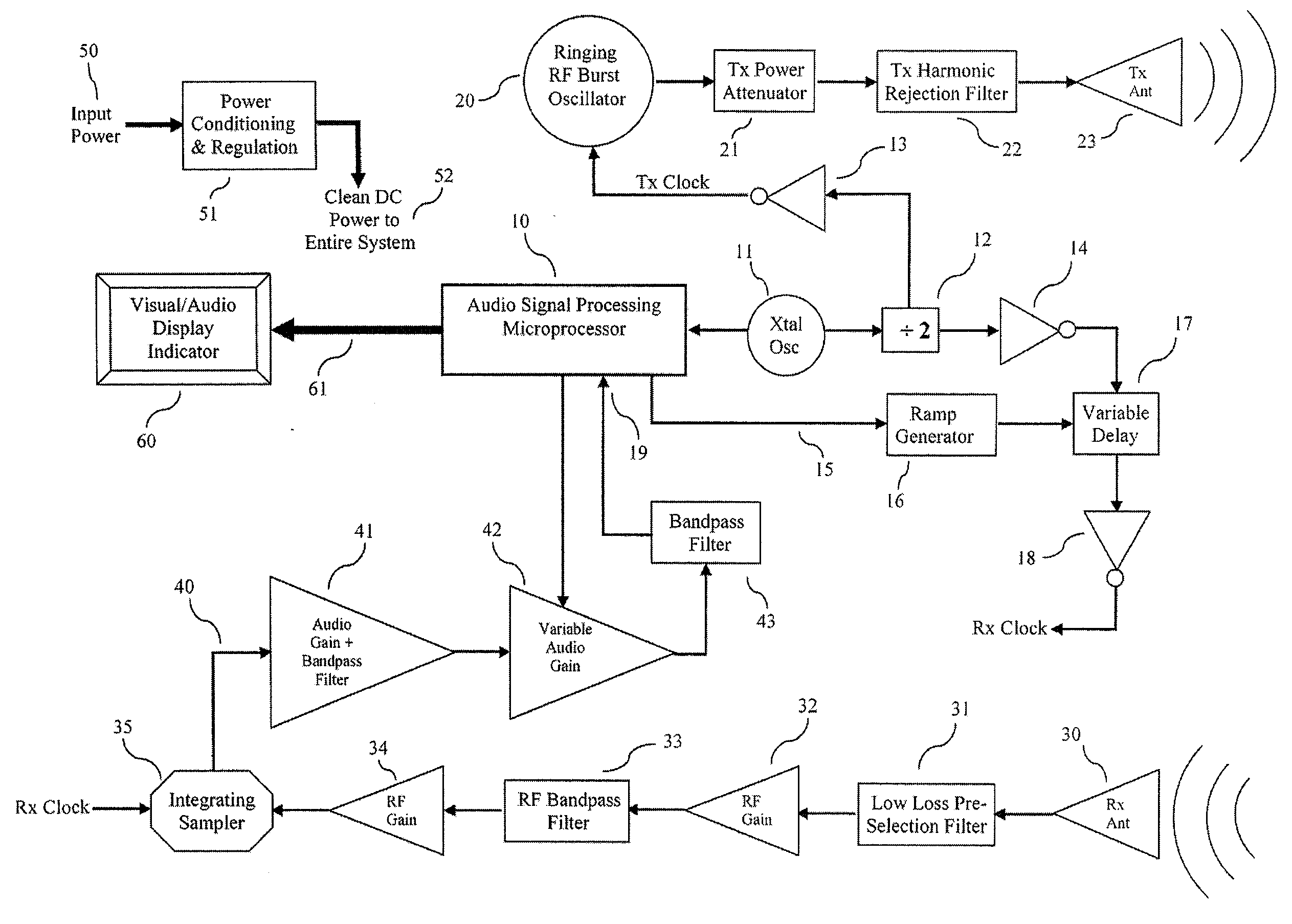
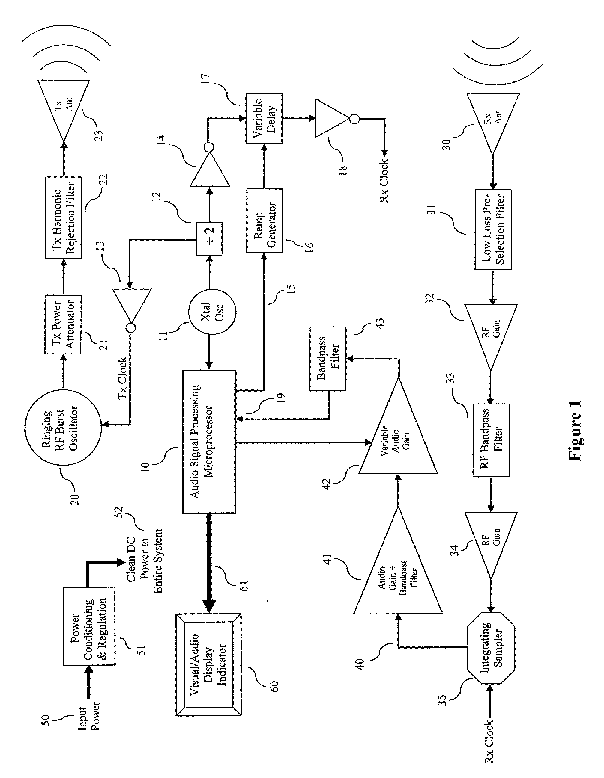
[0031]FIG. 1 shows a detailed functional block diagram of the radar system. The microprocessor 10 is at the heart of the radar system providing timing control, signal processing and analysis of the receiver signal and communication with a display and / or enunciator device 60. The microprocessor 10 can be any of a wide variety of low-cost products commonly available and which provide built-in audio signal digitization and mathematical signal processing capabilities.

[0032]Crystal oscillator 11 provides clocking signals for the microprocessor 10 as well as for the transmitter oscillator 20 and the receiver integrating sampler 35. The frequency of oscillation is a typically a few Meg...


PUM


Abstract

Pulsed radar detects the presence and range of very short-range objects via small perturbations in phase and/or amplitude of relatively long duration coherently related transmit pulses. In one embodiment, echoes forming a received signal waveform from a sampling baseband radar receiver are processed at audio frequency to look for perturbations of the phase of the time-stretched received radar signal while the radar is still transmitting a long-duration pulse. In a second embodiment, the time-stretched received signal is processed to look for perturbations in the amplitude of the received radar signal. Small amplitude perturbations due to constructive and destructive interference of the transmitted and reflected signals occur in the receiver when objects are very close to the radar if the receiver is not heavily saturated. These same techniques can also be used to achieve highly accurate ranging of long-distance objects and detection of overlapping echoes from multiple objects.

Description

CROSS-REFERENCES TO RELATED APPLICATIONS[0001]The present application claims benefit under 35 USC 119(e) of U.S. provisional Application No. 61 / / 093,573, filed on Sep. 2, 2008, entitled “Short Distance Range Resolution In Pulsed Radar,” the content of which is incorporated herein by reference in its entirety.STATEMENT AS TO RIGHTS TO INVENTIONS MADE UNDER FEDERALLY SPONSORED RESEARCH OR DEVELOPMENT[0002]NOT APPLICABLEREFERENCE TO A “SEQUENCE LISTING,” A TABLE, OR A COMPUTER PROGRAM LISTING APPENDIX SUBMITTED ON A COMPACT DISK[0003]NOT APPLICABLEBACKGROUND OF THE INVENTION[0004]The present invention relates to short-range pulsed radar systems. More particularly it relates to techniques for accurately determining the range of objects detected by short-range pulsed radar systems when the object is located closer than one-half of the pulse duration times the speed of electromagnetic propagation. This is particularly relevant for long-pulse-duration pulsed radars occupying a relatively n...

Claims


Application Information

Patent Timeline
Patent Type & Authority Applications(United States)
IPC IPC(8): G01S13/08
CPCG01S7/2923G01S7/34G01S13/50G01S13/36G01S7/038G01S13/103
Inventor BANDHAUER, BRIANCOLE, JONATHANHAYDEN, DOUGLAS TODDFADGEN, JOHN
Owner PRECO ELECTRONICS
Why Eureka
Try Eureka