

Deep tissue temperature probe constructions
- Summary
- Abstract
- Description
- Claims
- Application Information
AI Technical Summary
Benefits of technology
Problems solved by technology
Method used
Image

Examples
first embodiment
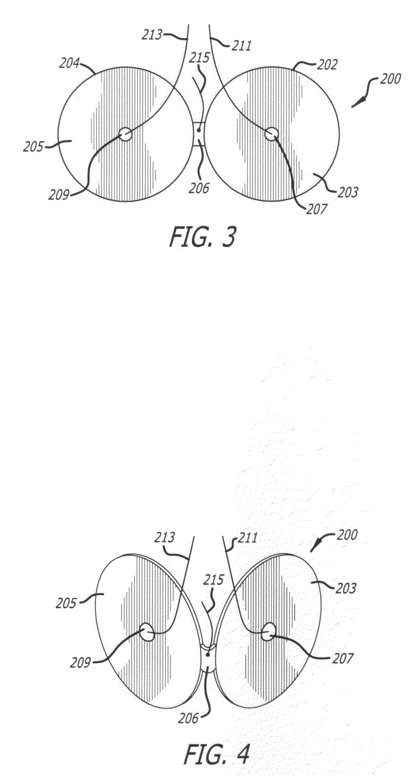
[0026]a support assembly for a DTT probe is illustrated in FIG. 3. The support assembly 200 includes a permanent heater (not shown) with an attachment mechanism (not shown) and is designed and manufactured to be disposable. The support assembly 200 includes a film of material coated with copper on both sides and fashioned into two disk-shaped sections 202 and 204 that are joined at a common peripheral location 206 disposed between the two sections. The disk shaped sections 202 and 204 include major supporting surfaces 203 and 205 respectively. The surfaces on the opposite sides of the major supporting surfaces 203, 205 (which are not seen in these figures) support respective thermocouples whose junctions 207, 209 are visible at the respective centers of the major supporting surfaces 203, 205. Signal leads 211, 213 are connected to the thermocouples at the junctions 207, 209, and a common lead 215 is electrically coupled to the thermocouples. Preferably, a pressure-sensitive adhesive...
second embodiment
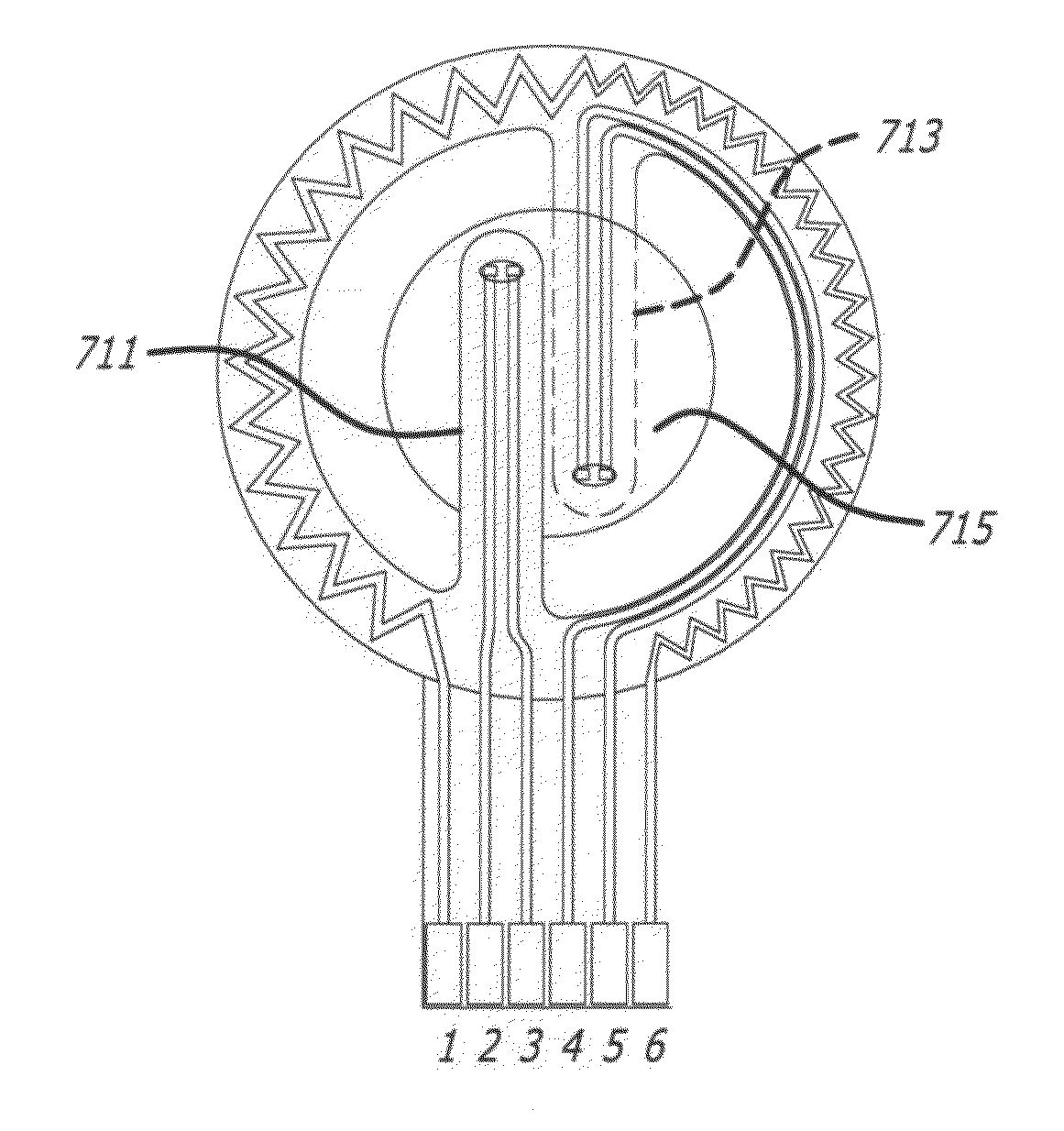
[0028]With reference to FIGS. 6-9, a support assembly 500 for a DTT probe includes a heater integrated into the support assembly. There are no wires attached to this embodiment as both signal and power leads are available on a connector tab on the circumference of the assembly.
[0029]As best seen in FIGS. 6 and 7, the support assembly 500 includes a flexible substrate, preferably a sheet of flexible, thermally insulative material that is formed to include a plurality of contiguous sections. For example three contiguous paddle-shaped sections with disks 502, 504, and 506 of equal diameter are formed and aligned so that their centers lie on a straight line. Each disk transitions to a tab for supporting one or more electrical leads. The tabs are indicated by reference numerals 503, 505, and 507, respectively. The inner periphery of each disk is continuous with each adjacent inner periphery at a point that is tangent to the perimeter of the inner circle and which intersects the line upon...
PUM
 Abstract
Description
Claims
Application Information