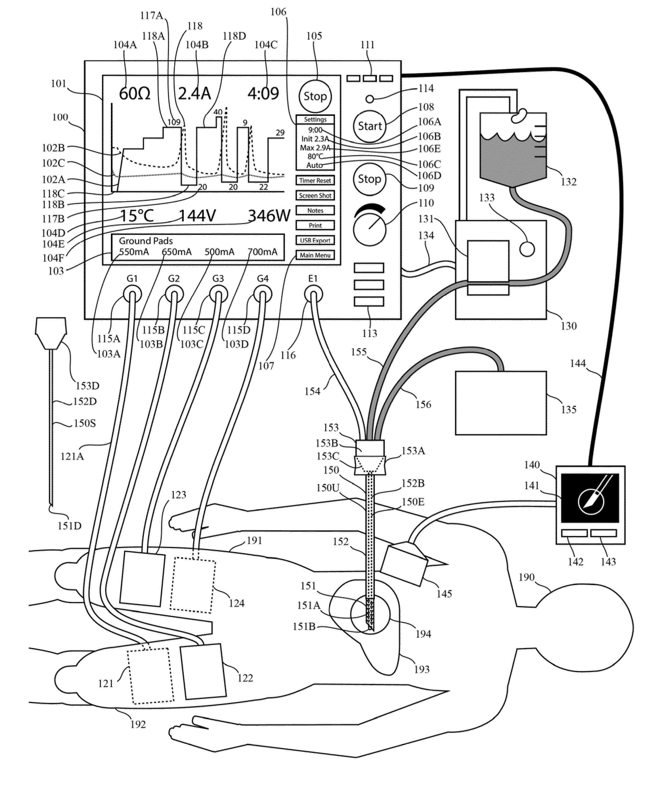
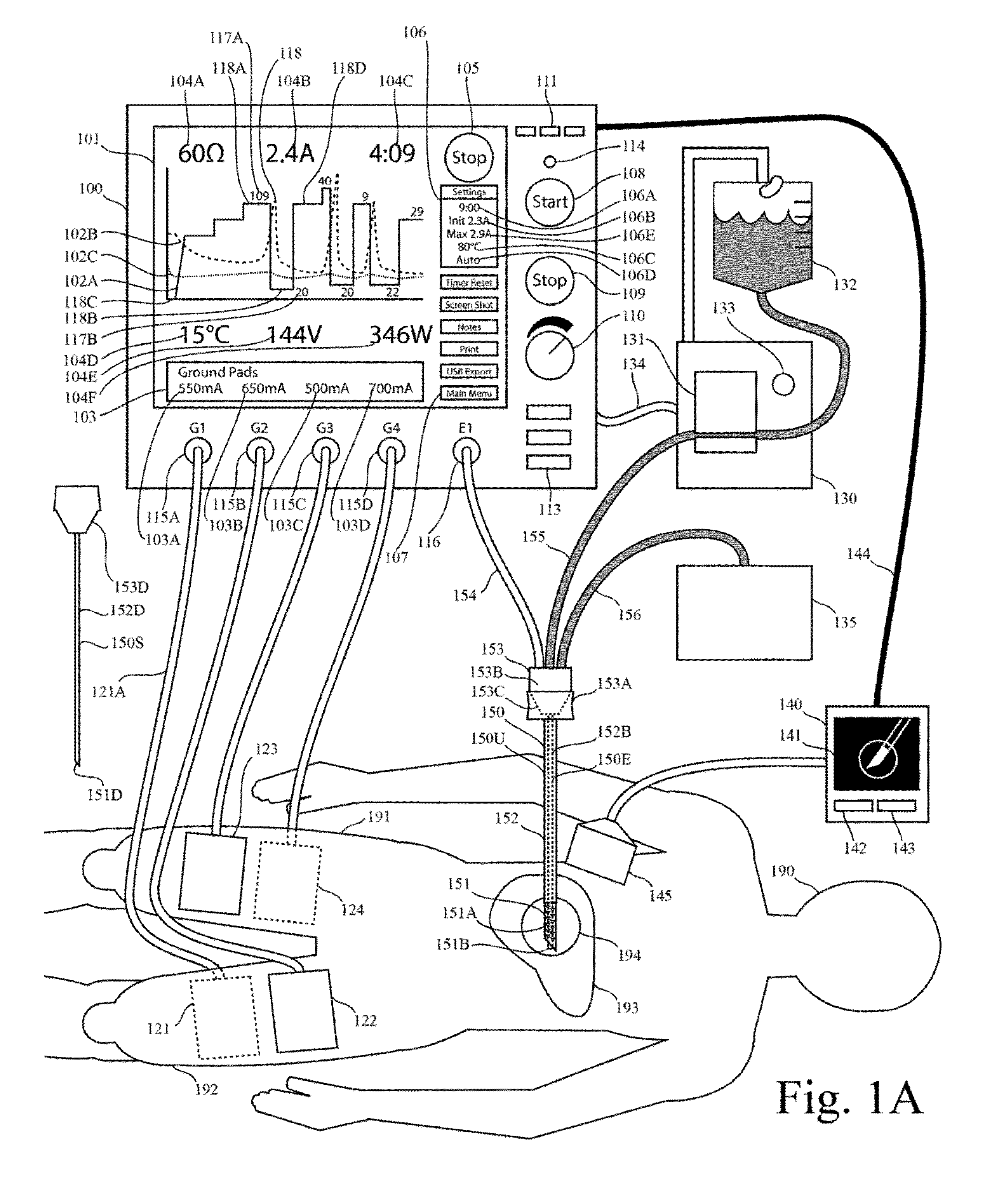
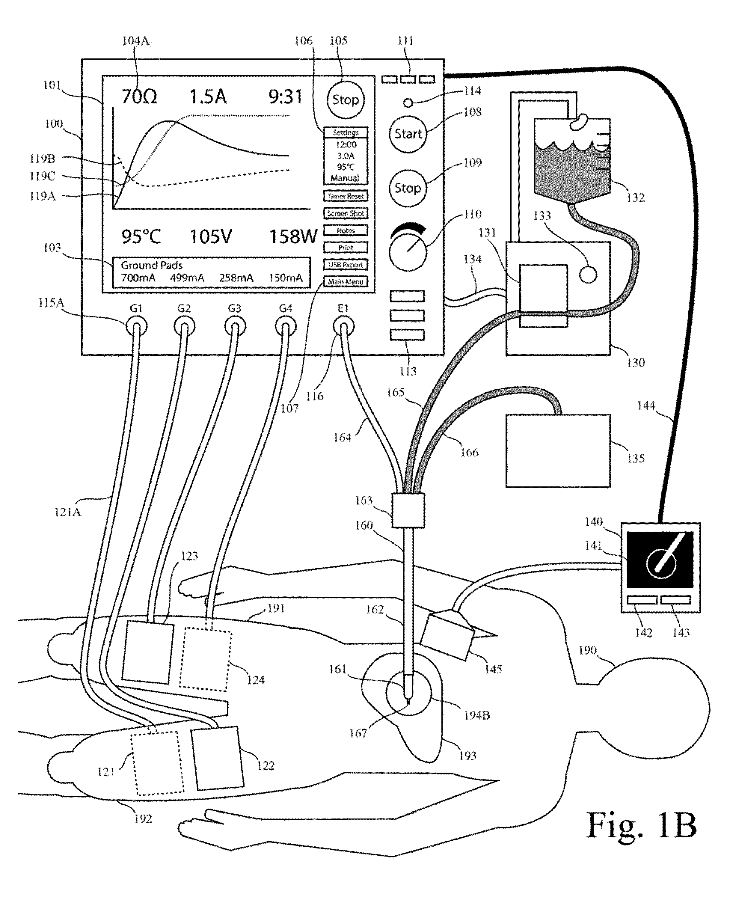
One limitation of these RF generators is that they do not provide real-time graphic display of impedance as function of time.
One limitation of these RF generators is that they do not provide real-time graphic display of current as function of time.
One limitation of these RF generators is that they do not provide real-time graphic display of both current and impedance as function oftime.
One limitation of these generators is that they do not provide real-time graphic display of both impedance and the generator output level as function of time.
One limitation of these generators is that they do not provide real-time graphic display of impedance, current, and temperature as function of time.
One limitation of these generators is that they do not provide real-time graphic display any two of the following
list: current,
voltage, power, impedance, or mathematical functions with these parameters as arguments.
One limitation of these RF generators that are configured for cooled RF tissue ablation by means of an automated impedance-driven pulsing process is that they do not provide a graphic display of any measured parameter as a function of time axis.
While some generator systems in the prior art have allowed for export of generator readings which could be used to plot parameters on the same time axis after the ablation procedure, this does not provide instant feedback that would allow a clinician to monitor the ablation process as it progresses and to make adjustments if necessary.
One limitation of '515 is that no parameter of the RF generator signal output level (eg volage, current, power) is plotted as a function of a time.
Another limitation of '515 is that the RF generator signal output level (eg
voltage, current, power) is not plotted on the same time axis as the impedance.
Another limitation of '515 is that the
system does not pertain to
RF ablation using an internally-cooled RF electrode.
Another limitation of '515 is that it does not pertain to automated methods of repeatedly pulsing the RF signal output.
One limitation of '725 is that the system does not pertain to
RF ablation using an internally-cooled RF electrode.
Another limitation of '725 is that it does not pertain to automated methods for impedance-
feedback control of a cooled RF electrode.
Another limitation of '725 is that it does not pertain to automated methods comprising repeated pulsing the RF signal output.
One challenge in cooled RF control by means of impedance-based pulsing methods is the selection of a target
radiofrequency signal level, eg current, that can produce a stable ablation process, because the maximum
signal level that particular tissue can carry without overheating and limiting ablation size, can vary across tissue types, patients, and bodily locations.
One limitation of the prior art in impedance-based pulsing methods for cooled
RF ablation control is that the initial output level ramp is too fast to discriminate the maximum output level ramp that the tissue can stably carry during the ablation process.
One limitation of the prior art in impedance-based pulsing methods for cooled RF ablation control is that the output level, namely the current level, does not increase from the initial set value during the ablation process.
One limitation of the prior art in impedance-based RF pulsing methods is that if the output level is set low to avoid the risk of overheating the tissue, then the maximum ablation size may not achieved, or the maximum
lesion size may be not achieved as efficiently as possible.
Another limitation of the prior art in pulsing methods for cooled RF ablation is that the “down times” (that is, the inter-pulse cooling times) do not vary during an ablation session.
This is an important limitation because the extent of the region of boiling tissue bubbles can change during the ablation process, and / or because the
heat distribution around the bubble zone changes the rate of dissipation of the bubbles, and / or because a predetermined down-
time duration may not be well matched to the every ablation
scenario, leading to a situation where more or less inter-pulse
cooling time is required for optimal dissipation of vapor bubbles in the tissue.
Another limitation of prior systems for RF tissue ablation is that they do not plot both the impedance and the generator output level (eg voltage, current, or power) on the same time axis in real time.
Another limitation in the prior art is that prior systems for RF tissue ablation do not include a plot of two or more of the parameters impedance, voltage, current, and power.
Another limitation in the prior art is that prior systems for RF tissue ablation do not include both an automatic method for output-level pulsing (eg for cooled RF tissue ablation) and a real-time graphical plot of a parameter of the generator output (eg voltage, current or power, impedance) as a function of time.
This can be a rapidly explosive process and an unstable process.
However, the
instability is reflected in other signal output parameters, including, for example, the signal
output impedance, power, current, and voltage.
One limitation of the prior art in Lee is that it does not provide for simultaneous activation of multiple ground pads at the same time during a switching sequence.
Another limitation of Lee is that the
peak current at each ground pad is identical and equal to the
total current delivered to one or more ablation electrodes.
Another limitation of the prior art in Lee is that the sequence of switch states is predetermined, alternating sequentially among a number of grond pads.
Another limitation of the prior art in Lee is that the sequence of switch states is not based on a measurement of a ground pad parameter.
Another limitation of the prior art in Lee is that a sequential ground-pad switching sequence does not generally minimize
tissue heating for each ground pad relative to other switching sequences.
Another limitation of the prior art in Lee is that a sequential ground-pad switching sequence does not maximize the total ablation current that a configuration of ground pads can carry, across all possible ground-pad switching sequences.
Another limitation of the prior art in Lee is that it does not provide a switching method that can control both the total rate of heating in tissue adjacent to two or more ground pads, and the rate of heating in the tissue region adjacent to each one of the said two or more ground pads.
Another limitation of Lee is that a cyclic switching sequence does not maximize the
total current which can be carried by a set of ground pads, where the RMS current each ground pad is held below a safety limit.
Another limitation is that the system of Lee does not reduce the number of switching transitions.
Another limitation is that the system of Lee does not provide for both switching and independent current-monitoring for each pad.
One limitation the papers of Schutt et al. is that they do not provide for control the current carried by any one of the ground pads in relative to a target current value or a maximum current value.
One limitation the papers of Schutt et al. is that they do not provide for
automatic control of the root-mean-squared (RMS) current at each pad over each
switching cycle.
Another limitation of the papers by Schutt et al. is that integration of temperature sensors into the ground pads is required.
One limitation preventing ground pad burns by
temperature monitoring is that the temperature sensor may not directly or reliably measure the temperature of heated tissue, for example, in the case where the ground pad is not fully adhered to the
skin.
Another limitation of the papers by Schutt et al. is that the relative position of the ground pad was known ahead of time and used to set up the switching process manually, rather than automatically by means of a controller based on a measured parameter of a ground pad.
Another limitation of the papers by Schutt et al., is that neither the ground-pad switch states (as reflected by the identities of the connected ground pads and disconnected ground pads) in the sequence, nor the order of the switch states in the sequence, was determined by an
automatic controller using a measured ground-pad parameter.
Another limitation of the papers by Schutt et al., is that the identity and order of switch states is predetermined.
Another limitation of the papers by Schutt et al. is that they do not provide for both switching and current monitoring at each pad individually.
Another limitation of the papers by Schutt et al. is that ground pad switch was used in conjunction with an ablation electrode output that was set to a
constant power, which can lead to variable
current density around the electrode active tip as ground pads are connected and disconnected, and thus potentially leading to inconsistent
lesion sizes at the ablation site.
Another limitation of the papers by Schutt et al. is that they do not provide for both switching and independent current-monitoring for each pad.
One limitation of adding resistance between a ground pad and the power supply is that generated electrical energy is dissipated in the resistance and does not heat the
target tissue, thereby limiting the maximum
heating power that the generator can produce.
One limitation of the prior art in '322 is that the variety of ground pad configurations to which the system can adapt is limited by the limited amount of resistance that is added to each ground pad line during an ablation procedure.
Another limitation of the prior art is that RF ablation systems configured for nerve ablation do not include means for connection and monitoring of multiple ground pads.
This is a significant limitation for energizing multiple nerve ablation electrodes in a
single patient at the same time, which can produce high currents in excess of current capacity of a single typical nerve-ablation ground pad.
Another limitation of the prior art on ground pad switching in Lee and Schutt et al. is that they do not provide for the prevention or reduction of electrical stimulation of excitable tissue that can occur due to transient direct-current signals that can arise when a switch opens or closes.
Undesired stimulation of excitable tissue can occur at
a site remote of the ground pads and ablation electrodes.
Undesired stimulation of nerves can occur, and be disturbing to the patient, due to high
electric field strengths near the active tip of an RF ablation electrode and transients produced by connection or disconnecting a ground pad from the source of the RF ablation signal.
One limitation the prior art in
ultrasound image guidance for tissue ablation is that the physican must use a two sets of controls to operate both the
ultrasound imaging device and the HF ablation generator.
In one example, the absence of a single
user interface for control and monitoring of both
ultrasound imaging and ablation readings is a limitation for ultrasound-guided cooled RF
tumor ablation using an RF pulsing process that repeatedly induces tissue boiling, because the ultrasound images and the RF generator readings both provide rich information to the operating physician who, as does the correlation of ultrasound features and features of RF generator readings (eg echogenic bubble formation and variations in RF impedance.
Another limitation of the prior art is the absence of automated influence of the ablation process using
ultrasound imaging data as an input.
One limitation of the prior art is that RF and nerve-stimulation signals are not applied at the same time to a single
peripheral nerve.
One limitation of the prior art is that RF and nerve-stimulation signals are not applied at the same time to a single
peripheral nerve, and firing in that nerve is not monitored at the same time.
One limitation of the prior art is that RF and nerve-stimulation signals are not repeatedly interleaved to provide for
nerve stimulation throughout an RF ablation process.
One limitation of the prior art is the response of a nerve to a stimulation single is not used as a stopping criteria for an RF nerve ablation.
Another limitation of the prior art is that an RF generator configured for nerve ablation does not produce
nerve stimulation signals that are configured to electrically block the transmission of action potentials within a nerve, such as a high-frequency block signal.


