Surgical scalpel with inductively heated regions

Active Publication Date: 2010-10-21
DOMAIN SURGICAL
View PDF101 Cites 33 Cited by
  • Summary
  • Abstract
  • Description
  • Claims
  • Application Information

AI Technical Summary

Benefits of technology

[0018]According to one aspect of the invention, a thermal surgical tool system is provided with a ferromagnetic coating over a conductor and an oscillating electrical energy source for generating heat at the location of the coating. The oscillating electrical energy may cause inductive heating of the ferromagnetic coating. Moreover, the

Problems solved by technology

The oscillating electrical energy may cause i

Method used


Image

  • Surgical scalpel with inductively heated regions
  • Surgical scalpel with inductively heated regions
  • Surgical scalpel with inductively heated regions

Examples


Embodiment Construction

[0077]The invention and accompanying drawings will now be discussed in reference to the numerals provided therein so as to enable one skilled in the art to practice the present invention. The drawings and descriptions are exemplary of various aspects of the invention and are not intended to narrow the scope of the appended claims.

[0078]As used herein, the term “ferromagnetic,”“ferromagnet,” and “ferromagnetism” refers to any ferromagnetic-like material that is capable of producing heat via magnetic induction, including but not limited to ferromagnets and ferrimagnets.

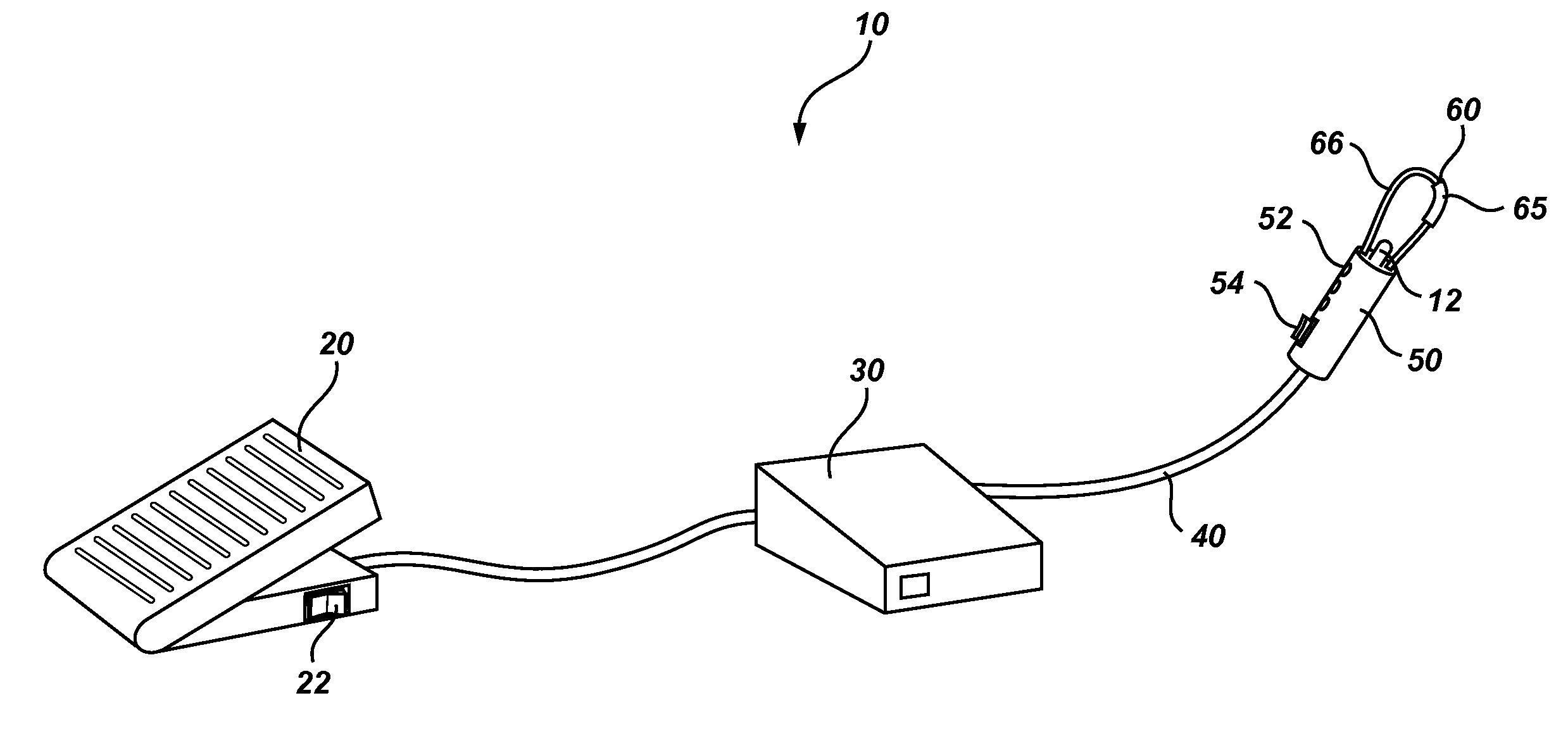
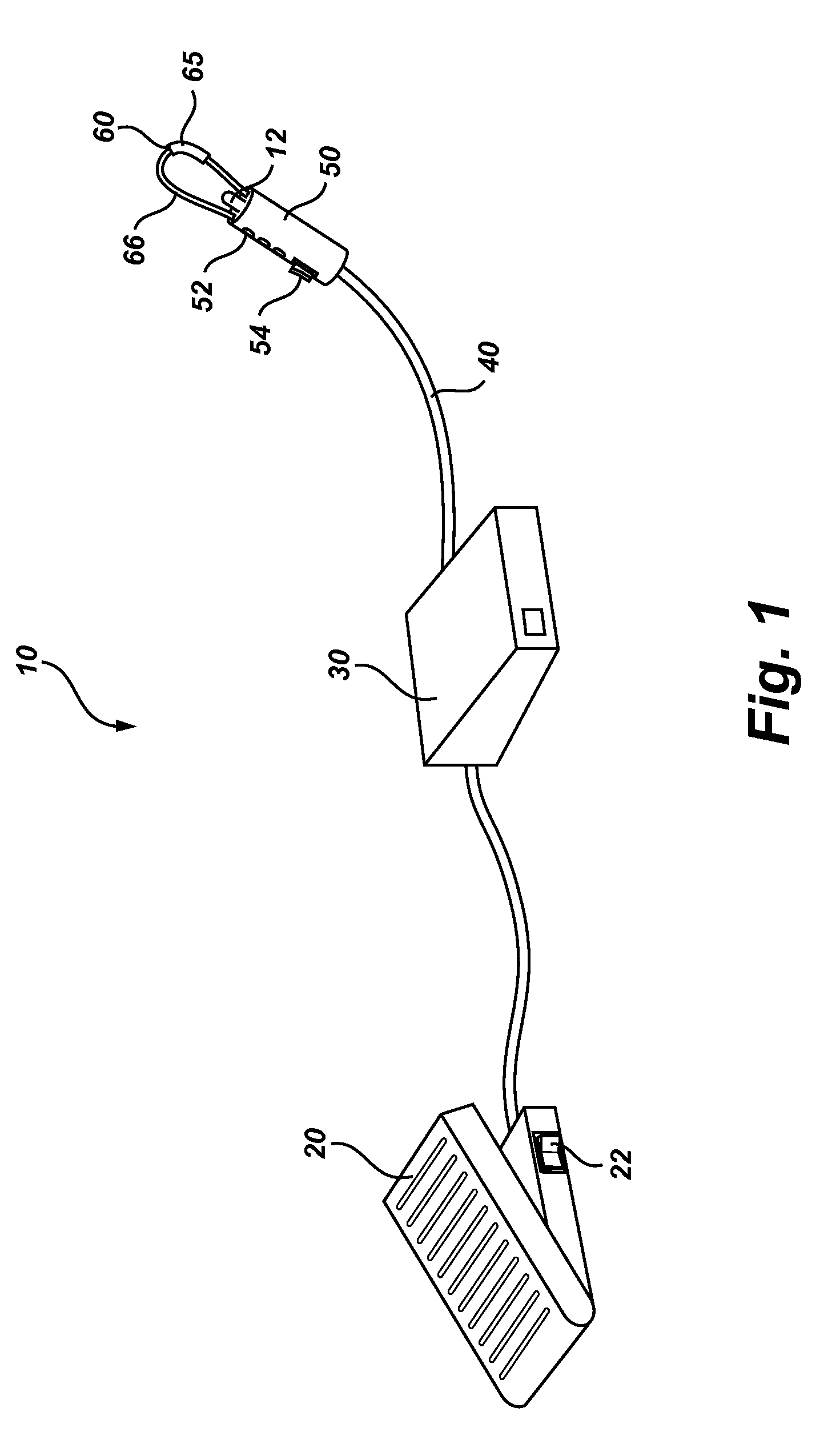
[0079]Turning now to FIG. 1, there is shown a perspective view of a thermal surgical tool system, generally indicated at 10. As will be discussed in additional detail below, the thermal tool system preferably uses a ferromagnetic coated conductor to treat or destroy tissue (i.e. endothelial tissue welding, homeostasis, ablation, etc).

[0080]It will be appreciated that the thermal surgical tool uses heat to incise tissue ...


PUM

PropertyMeasurementUnit
Temperatureaaaaaaaaaa
Poweraaaaaaaaaa
Energyaaaaaaaaaa

Abstract

An electrical conductor, such as a wire or catheter, which is coated circumferentially with a ferromagnetic material in a selected region, is fed from a high frequency alternating current source. The ferromagnetic material has a quick response in heating and cooling to the controllable power delivery. The ferromagnetic material can be used for separating tissue, coagulation, tissue destruction or achieving other desired tissue effects in numerous surgical procedures.

Description

RELATED APPLICATIONS[0001]The present application claims the benefit of U.S. Provisional Patent Application Ser. No. 61 / 170,203, filed Apr. 17, 2009, U.S. Provisional Patent Application Ser. No. 61 / 170,220, filed Apr. 17, 2009, and U.S. Provisional Patent Application Ser. No. 61 / 170,207, filed Apr. 17, 2009, which are incorporated hereby by references in their entirety.[0002]This application is part of a group of similar applications including U.S. patent application Ser. No. 12 / 647,340, filed Dec. 24, 2009, Attorney Docket Number 4340.NEXS.NP; U.S. patent application Ser. No. 12 / 647,344, filed Dec. 24, 2009, Attorney Docket Number 4340.NEXS.NP2; U.S. patent application Ser. No. ______ filed Dec. 24, 2009, Attorney Docket Number 4340.NEXS.NP4; U.S. patent application Ser. No. ______ filed Dec. 24, 2009, Attorney Docket Number 4340.NEXS.NP5; U.S. patent application Ser. No. ______ filed Dec. 24, 2009, Attorney Docket Number 4340.NEXS.NP6; U.S. patent application Ser. No. ______ filed...

Claims


Application Information

Patent Timeline
IPC IPC(8): A61B18/08A61B17/32
CPCA61B2018/00642Y10T29/49124A61B2018/00107A61B18/08A61M25/00A61B18/082A61B18/10A61B2017/32007A61B2017/320082A61B2017/320069A61B18/04A61B18/12A61L31/08A61B2018/00791A61B2018/00702A61B18/085A61B2018/1412A61B17/320068A61B2017/00141A61B2017/00876A61B2017/00973A61B2018/00077A61B2018/00654A61B2018/00714A61B2018/00755A61B2018/00803A61B17/00234A61B17/3211A61B2018/00577A61B2018/00589A61B2018/00595A61B2018/00619A61M25/0082A61B18/1206A61B18/1492A61B2018/00095A61B2018/0013A61B2018/00601A61B2018/00958A61B2018/128A61B2018/1407
Inventor MANWARING, KIMMCNALLY, DAVID
Owner DOMAIN SURGICAL
Why Eureka
Try Eureka