[0006]The present invention provides a gas piston
operating system for a firearm that pre-tensions the mechanical linkage to reduce or eliminate loose fits and / or physical gaps and clearances between linkage components that may cause rattling, wear, or damage of the gas system linkage-related components described above. In addition, maintaining tight tolerances and clearances is desirable for user-replaceable firearm barrels as described herein where proper clearances between parts are necessary to make implementation of a quick change
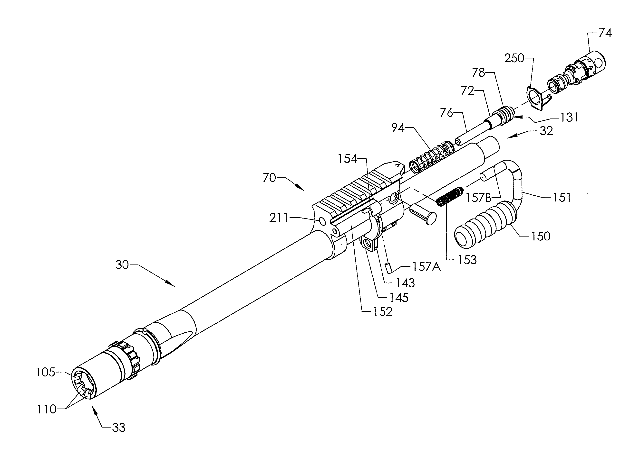
barrel system possible and expedient. In a preferred embodiment, the present invention provides staged piston actuation including an initial first partial actuation stage in which a reduced cross-section of the piston is exposed to the full pressure force of the gas followed by a second full piston actuation stage in which is the full piston cross-section is exposed to the full pressure force of the gas. The initial piston actuation stage functions to reduce the initial peak force generated by the
combustion gas
propellant, and puts all parts or linkages of the piston actuation system in contact, which in one embodiment includes an axially movable operating or transfer rod that operably links the piston to the bolt carrier. The second full piston actuation stage then completes movement of the entire action after all parts or linkages of the piston actuation system have been placed into contact with each other during the initial first partial piston actuation stage. The linkage pre-tensioning mechanism is further intended to reduce
impact forces and stresses between the piston, transfer rod, and bolt carrier to minimize component failures and operating problems by eliminating physical gaps that may exist between these components prior to discharging the firearm.
[0008]In operation, as further described herein, the 2-stage gas piston is intended to minimize the effect of the peak of the typical
pressure curve associated with the combustion gas generated in the firearm
barrel by igniting the
cartridge propellant. In one embodiment, a smaller reduced
diameter protrusion such as an axially extending stud may be formed on the face of the piston that produces a smaller force than the full
diameter piston would make at peak combustion
gas pressure. The stud is preferably inserted into a reduced
diameter passageway leading from the barrel bore to the full piston bore that slidably receives the piston. As the piston (and the autoloading action) moves, the pressure from the combustion of the
propellant begins to decrease after initial ignition of the propellant. As the piston stud moves out of the reduced diameter passageway, which in some embodiments be part of a user-adjustable
pressure regulator, the entire piston bore becomes pressurized, but by now, the combustion
gas pressure has also dropped. At this point, the full face of the piston (including the stud) is now exposed to the
gas pressure. This larger piston diameter compensates for the lower gas pressure, resulting in a more even and higher force that is applied to the action over the entire
stroke of the piston. Accordingly, the initial higher
peak pressure has produced a lower piston actuating force and the subsequent lower pressure later in the
stroke has produced a higher force. This staged piston actuation operating method advantageously reduces wear of and increases the life of components, improves reliability because of a longer
power stroke with less peak force on the piston, and the lower peak force upsets the barrel less, allowing the bullet to escape the barrel before the forces from the gas system disturb the barrel alignment to the target.
[0014]According to another aspect of the invention, an improved bolt carrier operable for reciprocating movement in a
receiver of a gas operated
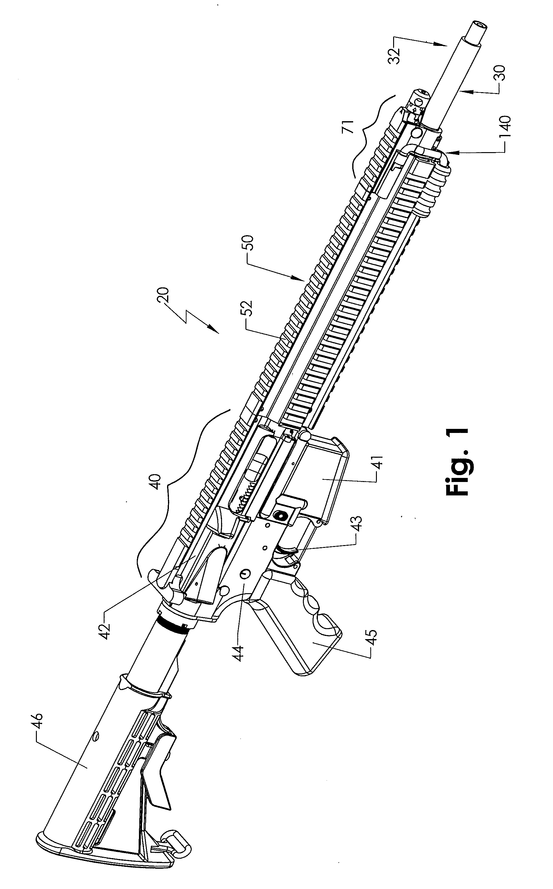
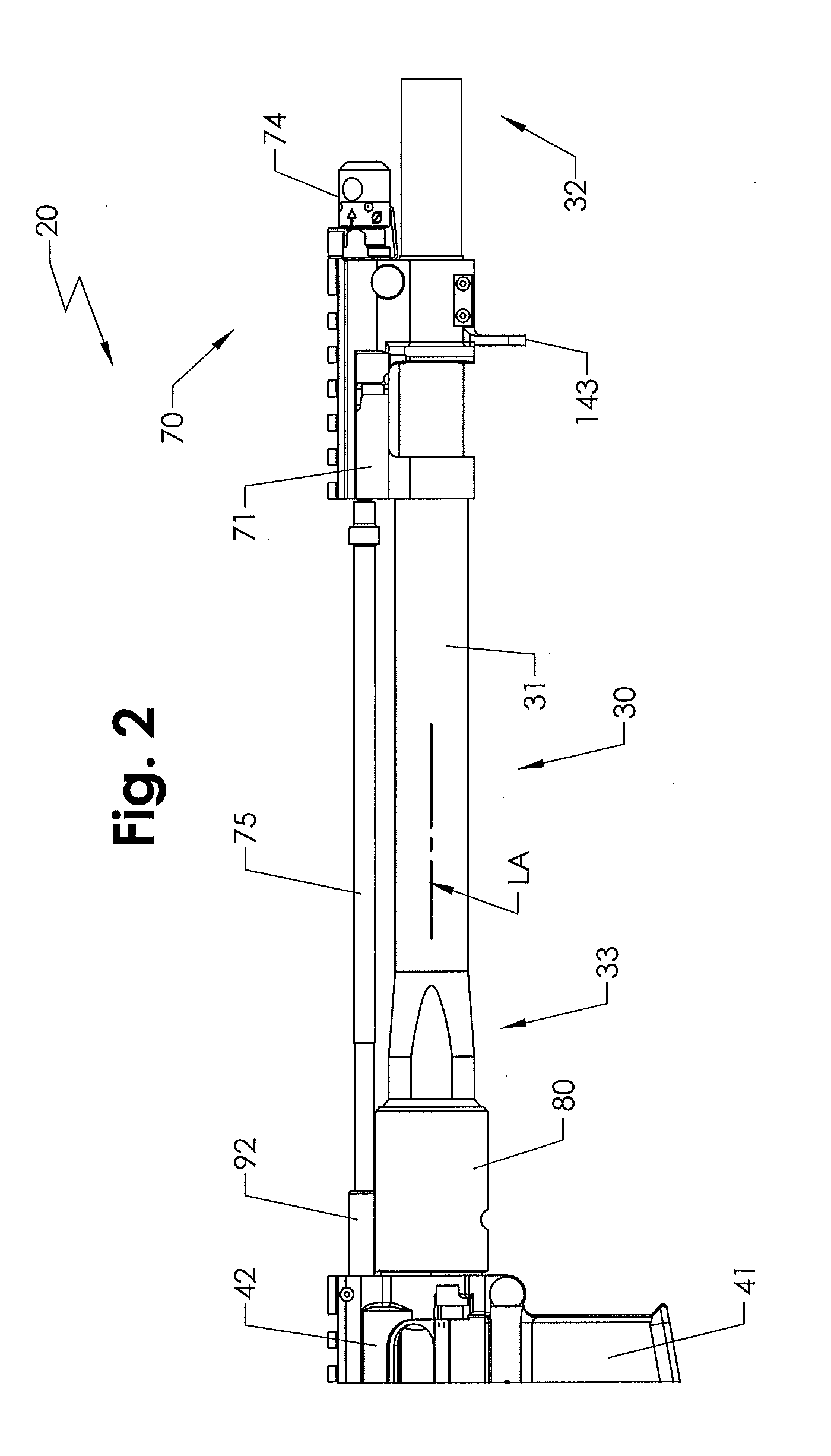
rifle is provided that reduces receiver wear. In one embodiment, the bolt carrier includes an elongated body having a front end and a front supporting section, a rear end and a rear supporting section, and a middle portion or span disposed therebetween. The bolt carrier is slidably disposed in the receiver and movable between a forward position and a rearward position therein to cycle the action of the
rifle for automatically unloading and loading cartridges into the chamber of the
rifle from a
magazine. Preferably, the middle portion is unsupported by the receiver and is further configured and sized not engage the receiver.
[0015]According to another embodiment, a rifle having a receiver and an improved bolt carrier includes a receiver defining an elongated
internal cavity having inner sliding surfaces and a generally cylindrical bolt carrier slidably disposed in the cavity of the receiver for axial reciprocating movement. The bolt carrier may include a front end and a rear end, a front supporting section
proximate to the front end, the front supporting section being sized and configured to engage the sliding surfaces of the receiver, a rear supporting section
proximate to the rear end, the rear supporting section being sized and configured to engage the sliding surfaces of the receiver, and a reduced diameter middle portion disposed between the front and rear supporting sections. The middle portion is sized and configured to prevent engagement with the sliding surfaces of the receiver when mounted therein such that the bolt carrier is operable in response to discharging the rifle to travel from an unactuated forward position to a rearward actuated position without the middle portion of the bolt carrier engaging the receiver.
[0016]According to another embodiment, a rifle having a receiver and an improved bolt carrier includes a receiver defining an elongated
internal cavity having inner sliding surfaces and a generally cylindrical bolt carrier slidably disposed in the cavity of the receiver for axial reciprocating movement. The bolt carrier includes a front end and a rear end, a front supporting section
proximate the front end and defining a first
load bearing diameter sized to engage the sliding surfaces of the receiver, a rear supporting section proximate the rear end and defining a second
load bearing diameter sized to engage the sliding surfaces of the receiver, and a reduced diameter middle portion disposed between the front and rear supporting sections. The middle portion defines a maximum non-load-bearing diameter smaller than the first and second load-bearing diameters to prevent engagement with the sliding surfaces of the receiver when mounted therein. The bolt carrier is operable in response to discharging the rifle to travel from an unactuated forward position to a rearward actuated position without the middle portion of the bolt carrier engaging the receiver.
[0018]According to another embodiment, a rifle having a receiver and an improved bolt carrier includes a receiver defining an elongated
internal cavity having inner sliding surfaces and a generally cylindrical bolt carrier slidably disposed in the cavity of the receiver for axial reciprocating movement, the bolt carrier including a front end, a rear end, and a middle portion disposed between the ends. The rifle further includes a bolt carrier
support system consisting of a front supporting section located proximate to the front end and defining a first
load bearing surface having a first diameter sized to engage the sliding surfaces of the receiver, and a rear supporting section located proximate to the rear end defining a second load
bearing surface having a second diameter sized to engage the sliding surfaces of the receiver. The middle portion has a
maximum diameter smaller than the first and second diameters to prevent engagement with the sliding surfaces of the receiver when the bolt carrier reciprocates in the receiver in response to discharging the rifle.


