Magnetic components and methods of manufacturing the same

a technology of magnetic components and manufacturing methods, applied in the direction of magnetic bodies, transformers/inductances, magnetic cores, etc., can solve the problems of increasing prone to core cracking, and difficulty in winding the coil in a cost effective and reliable manner, so as to reduce the overall size of such devices, increase the cost of electronic components, and reduce manufacturing processes. the effect of cos

Inactive Publication Date: 2010-10-28
EATON INTELLIGENT POWER LTD
View PDF27 Cites 73 Cited by
  • Summary
  • Abstract
  • Description
  • Claims
  • Application Information

AI Technical Summary

Benefits of technology

[0004]With advancements in electronic packaging, the manufacture of smaller, yet more powerful, electronic devices has become possible. To reduce an overall size of such devices, electronic components used to manufacture them have become increasingly miniaturized. Manufacturing electronic components to meet such requirements presents many difficulties, thereby making manufacturing processes more expensive, and undesirably increasing the cost of the electronic components.
[0005]Manufacturing processes for magnetic components such as inductors and transformers, like other components, have been scrutinized as a way to reduce costs in the highly competitive electronics manufacturing business. Reduction of manufacturing costs is particularly desirable when the components being manufactured are low cost, high volume components. In high volume, mass production processes for such components, and also electronic devices utilizing the components, any reduction in manufacturing costs is, of course, significant.

Problems solved by technology

Especially for small core pieces, winding the coil in a cost effective and reliable manner is challenging.
Hand wound components tend to be inconsistent in their performance.
The shape of the core pieces renders them quite fragile and prone to core cracking as the coil is wound, and variation in the gaps between the core pieces can produce undesirable variation in component performance.
A further difficulty is that the DC resistance (“DCR”) may undesirably vary due to uneven winding and tension during the winding process.
The manufacture of transformer components presents similar challenges as inductor components.
For increasingly miniaturized components, providing physically gapped cores is challenging.
Establishing and maintaining consistent gap sizes is difficult to reliably accomplish in a cost effective manner.
A number of practical issues are also presented with regard to making the electrical connection between the coils and the terminal clips in miniaturized, surface mount magnetic components.
A rather fragile connection between the coil and terminal clips is typically made external to the core and is consequently vulnerable to separation.
This has proven tedious, however, from a manufacturing perspective and easier and quicker termination solutions would be desirable.
Additionally, wrapping of the coil ends is not practical for certain types of coils, such as coils having rectangular cross section with flat surfaces that are not as flexible as thin, round wire constructions.
The larger the wire gauge, however, the more difficult it is to flatten the ends of the coil to suitably connect them to the terminal clips.
Such difficulties have resulted in inconsistent connections between the coil and the terminal clips that can lead to undesirable performance issues and variation for the magnetic components in use.
Reducing such variation has proven very difficult and costly.
Fabricating the coils from flat, rather than round conductors may alleviate such issues for certain applications, but flat conductors tend to be more rigid and more difficult to form into the coils in the first instance and thus introduce other manufacturing issues.
Forming such features into the ends of the coils, however, can introduce further expenses in the manufacturing process.
Recent trends to reduce the size, yet increase the power and capabilities of electronic devices present still further challenges.
Meeting such requirement presents still further difficulties.
Still other difficulties are presented for components that are connected to multi-phase electrical power systems, wherein accommodating different phases of electrical power in a miniaturized device is difficult.
However, many known terminal clips used with magnetic components have a tendency to increase the footprint and / or the profile of the component when surface mounted to a circuit board.
That is, the clips tend to extend the depth, width and / or height of the components when mounted to a circuit board and undesirably increase the footprint and / or profile of the component.

Method used


Image

  • Magnetic components and methods of manufacturing the same
  • Magnetic components and methods of manufacturing the same
  • Magnetic components and methods of manufacturing the same

Examples


Embodiment Construction

[0029]Exemplary embodiments of inventive electronic component designs are described herein that overcome numerous difficulties in the art. To understand the invention to its fullest extent, the following disclosure is presented in different segments or parts, wherein Part I discusses particular problems and difficulties, and Part II describes exemplary component constructions and assemblies for overcoming such problems.

I. INTRODUCTION TO THE INVENTION

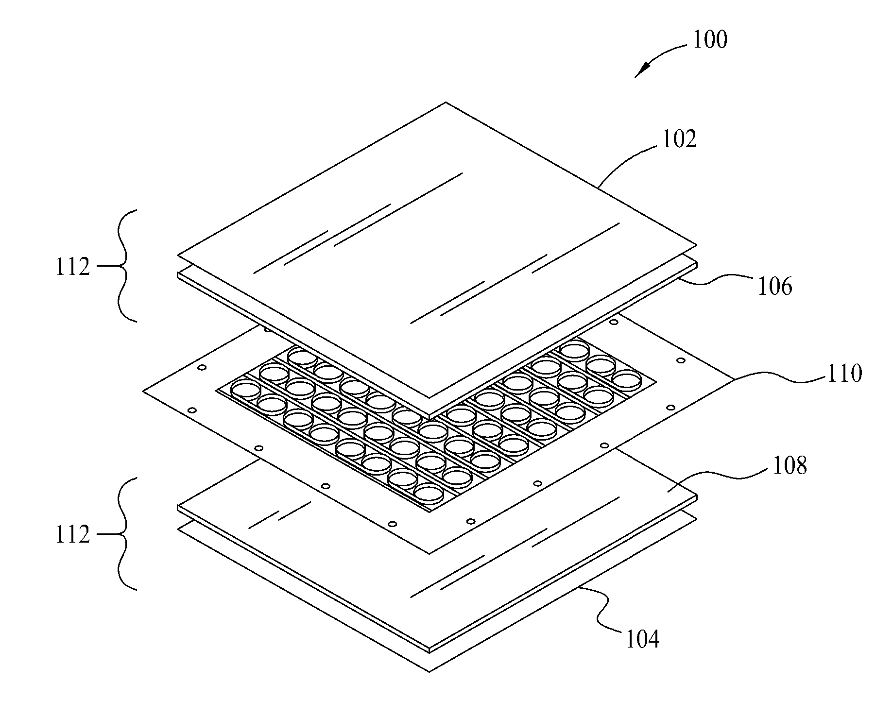
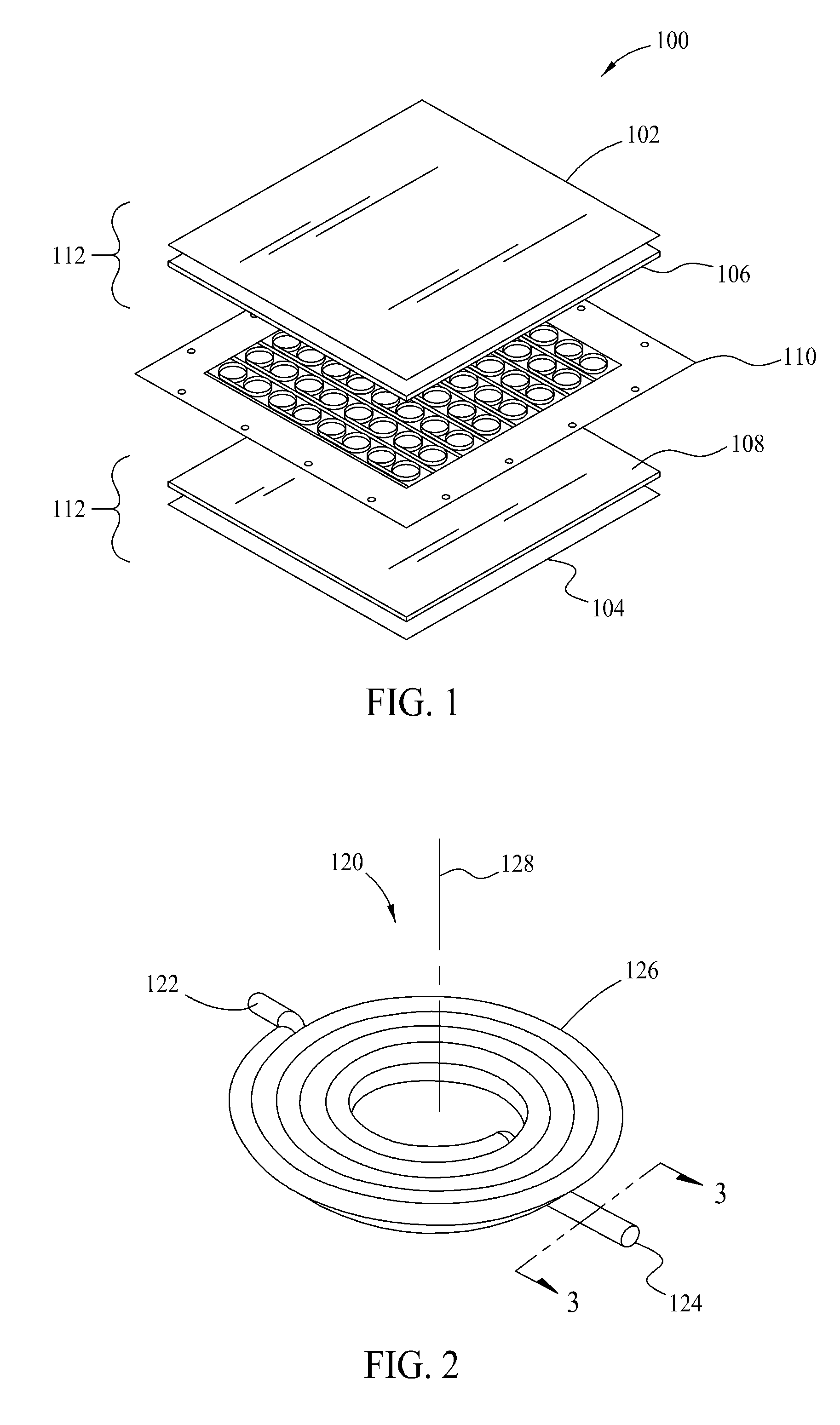
[0030]Conventional magnetic components such as inductors for circuit board applications typically include a magnetic core and a conductive winding, sometimes referred to as a coil, within the core. The core may be fabricated from discrete core pieces fabricated from magnetic material with the winding placed between the core pieces. Various shapes and types of core pieces and assemblies are familiar to those in the art, including but not necessarily limited to U core and I core assemblies, ER core and I core assemblies, ER core and ER co...


PUM

PropertyMeasurementUnit
temperaturesaaaaaaaaaa
conductiveaaaaaaaaaa
temperatureaaaaaaaaaa

Abstract

Magnetic component assemblies including moldable magnetic materials formed into magnetic bodies, at least one conductive coil, and termination features are disclosed that are advantageously utilized in providing surface mount magnetic components such as inductors and transformers.

Description

CROSS REFERENCE TO RELATED APPLICATIONS[0001]This application claims the benefit of U.S. Provisional Application Ser. No. 61 / 175,269 filed May 4, 2009, is continuation in part application of U.S. application Ser. No. 12 / 247,821 filed Oct. 8, 2008, and also claims the benefit of U.S. Provisional Patent Application No. 61 / 080,115 filed Jul. 11, 2008, the complete disclosures of which are hereby incorporated by reference in their entirety.[0002]The present application also relates to subject matter disclosed in the following commonly owned and co-pending patent applications: U.S. patent application Ser. No. 12 / 429,856 filed Apr. 24, 2009 and entitled “Surface Mount Magnetic Component Assembly”; U.S. patent Ser. No. 12 / 181,436 filed Jul. 29, 2008 and entitled “A Magnetic Electrical Device”; U.S. patent application Ser. No. 12 / 138,792 filed Jun. 13, 2008 and entitled “Miniature Shielded Magnetic Component”; and U.S. patent application Ser. No. 11 / 519,349 filed June Sep. 12, 2006 and enti...

Claims


Application Information

Patent Timeline
Patent Type & Authority Applications(United States)
IPC IPC(8): H01F27/24H01F27/29
CPCH01F1/14H01F1/14758H01F1/14791H01F1/15375H01F1/26H01F1/37H01F2017/048H01F17/04H01F27/255H01F27/2847H01F41/0246H01F2017/046H01F3/10
Inventor YAN, YIPENGBOGERT, ROBERT JAMES
Owner EATON INTELLIGENT POWER LTD
Why Eureka
Try Eureka