Device for and method of ray tracing wave front conjugated aberrometry

a technology of aberrometry and wavefront, applied in the field of ophthalmic examination instruments, can solve the problems of high cost of conjugation with active optics, subjective perception,

Inactive Publication Date: 2010-10-28
MOLEBNY VASYL
View PDF0 Cites 22 Cited by
  • Summary
  • Abstract
  • Description
  • Claims
  • Application Information

AI Technical Summary

Problems solved by technology

Unfortunately, as noted C. Campbell (U.S. Pat. No. 7,128,416), the adjusted shape of the deformable mirror does not directly indicate to the physician the actual aberrations of the patient's eye.
Consequently, it is often required to apply a complicated calibration scheme so that the control signals used to deform the deformable mirror may be correlated with the aberrations from the patient's eye that the deformed mirror removes.
Still another drawback is in involvement of subjective perception in some of the above reviewed techniques to judge how perfect the conjugation is made.
Still another problem of wave front conjugation with active optics is its high cost, especially when using photolithographic high spatial density MEMS (Micro-Electro-Mechanical Structure) technologies (F.-Y.

Method used


Image

  • Device for and method of ray tracing wave front conjugated aberrometry
  • Device for and method of ray tracing wave front conjugated aberrometry
  • Device for and method of ray tracing wave front conjugated aberrometry

Examples


Embodiment Construction

[0042]The embodiments of a device for and a method of ray tracing wave front conjugated aberrometry according to the present invention will be described in detail hereinafter with reference to the accompanying drawings.

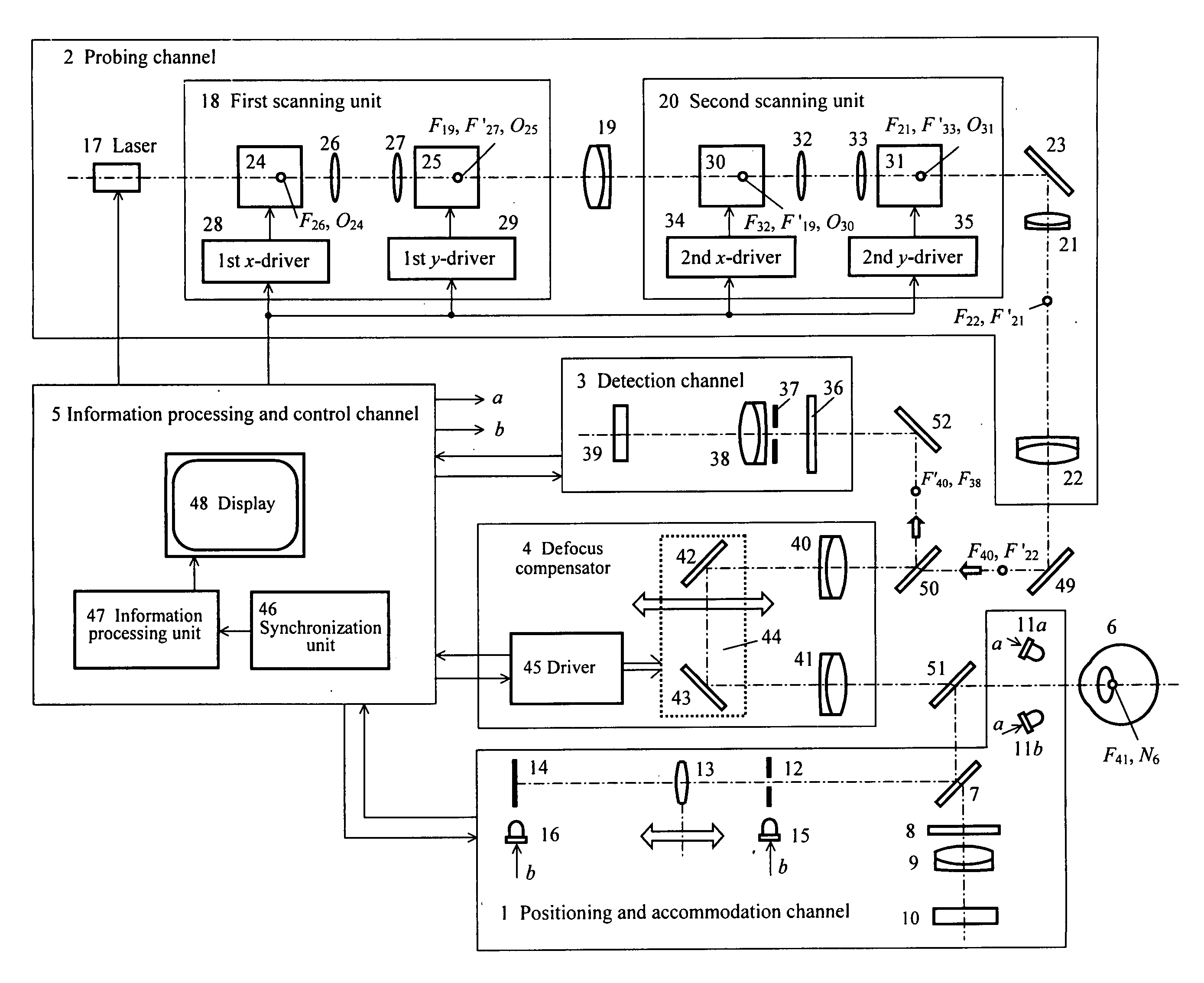
[0043]As shown in FIG. 1, the device contains a positioning and accommodation channel 1, a probing channel 2, a detection channel 3, a defocus compensator 4, and an information processing and control channel 5. The eye 6 is the object of investigation.

[0044]The positioning and accommodation channel 1 consists of a beam-splitter 7, a filter 8, an objective lens 9, an imaging camera 10 which can be a TV camera. Several sources of light 11, for example, light emitting diodes (LEDs) are installed in front of the eye 6. Two of them, 11a and 11b are shown in the FIG. 1. The positioning and accommodation channel 1 also includes a near target 12, a lens 13, and a far target 14. The lens 13 is movable along the optical axis. The near target 12 is illuminated by a source of lig...


PUM


Abstract

Two stages of ray tracing aberrometry include preliminary stage of measurement with probing beams successively entering the eye in parallel to the optical axis and the main stage of measurement with probing beams successively entering the same points of the eye but tilted in the way to compensate for the refraction variations over the entrance aperture measured in the preliminary stage. The main stage of measurement may be implemented in the combination of units, one compensating for defocus another—compensating for higher order aberrations. In one embodiment, the probing channel contains two two-coordinate acousto-optic deflectors with a collimating lens between them. The procedure of main stage of measurement may be iteratively repeated until the wave front conjugation is achieved with a prescribed accuracy.

Description

FIELD OF THE INVENTION[0001]The present invention relates to ophthalmic instruments that are used to examine the eye, in particular to ophthalmic examination instruments that measure and characterize the aberrations of the human eye, especially to those of them that provide high accuracy of measurements.BACKGROUND OF THE INVENTION[0002]Early instruments for measurement of aberrations of the human eye, called also instruments for wave front measurement, used the feedback that could be subjective or objective (setting the feedback signal to zero). Examples of such systems were described by S. M. Smirnov (Measurement of the wave aberration of the human eye. Biophysics, 1961, No. 6, pp. 776-795) and C. M. Penney et al (U.S. Pat. No. 5,258,791).[0003]The tendency to automate the measurements and make them faster resulted in several commercialized technologies. One of them is Hartmann-Shack wave front sensor whose principle was borrowed from the astronomy and military applications by J. L...

Claims


Application Information

Patent Timeline
Patent Type & Authority Applications(United States)
IPC IPC(8): A61B3/10
CPCA61B3/1015
Inventor MOLEBNY, VASYL
Owner MOLEBNY VASYL
Why Eureka
Try Eureka