Vacuum insulating glass unit including infrared meltable glass frit, and/or method of making the same

a technology of vacuum insulating glass and infrared meltable glass, which is applied in the direction of manufacturing tools, transportation and packaging, and plastic layered products, etc., can solve the problems of undesirable high temperature and long heating time of the entire assembly used in the formulation of edge seals b>4, >, and adversely affect certain low-e coatings, so as to increase the likelihood of glass deformation and/or breakage

Active Publication Date: 2010-11-04
GUARDIAN GLASS LLC
View PDF24 Cites 52 Cited by
  • Summary
  • Abstract
  • Description
  • Claims
  • Application Information

AI Technical Summary

Benefits of technology

[0010]Another advantage associated with not heating up the entire unit for too long is that lower temperature pillar materials may then be used. This may or may not be desirable in some instances.
[0011]Even when non-tem

Problems solved by technology

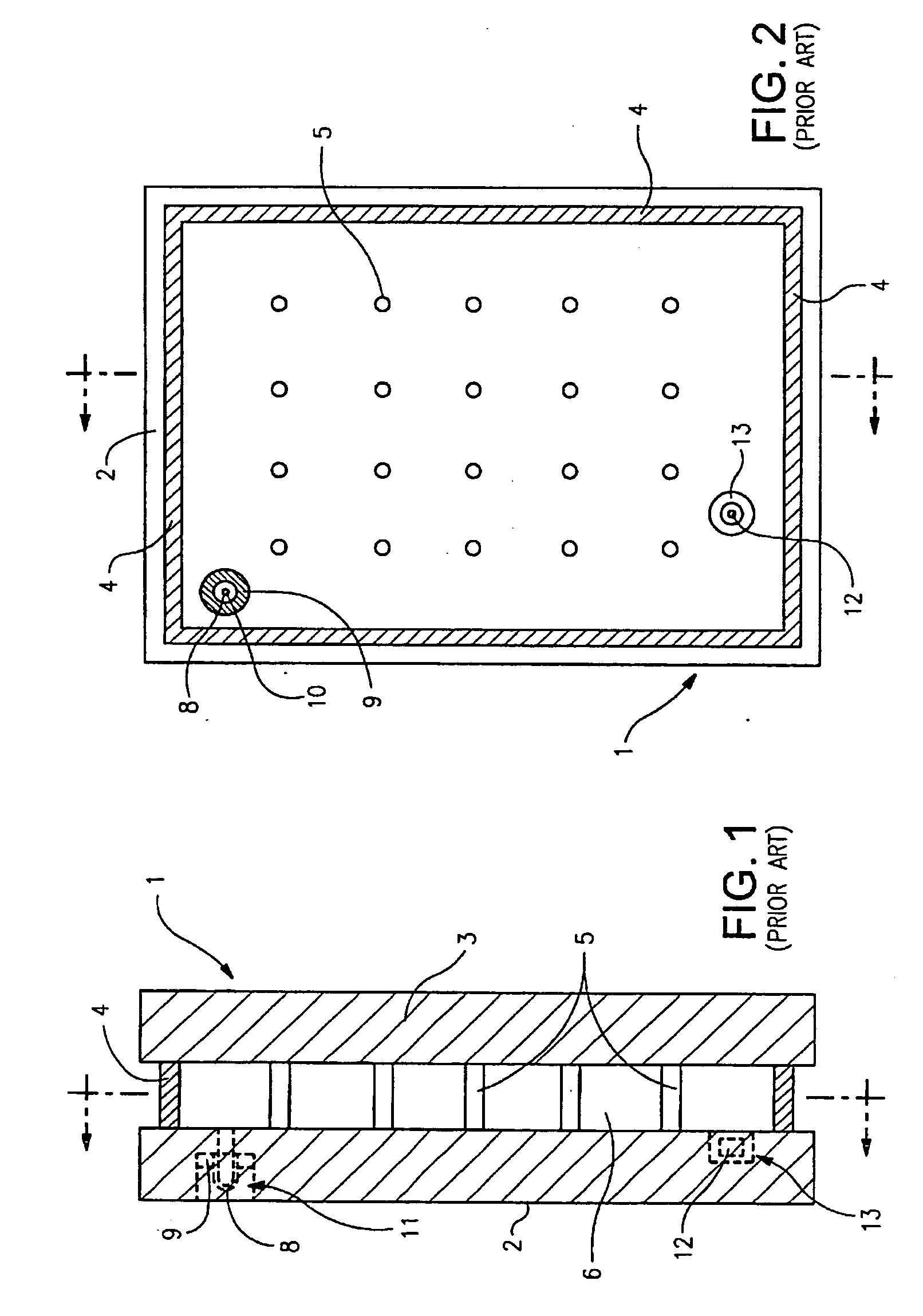
Unfortunately, the aforesaid high temperatures and long heating times of the entire assembly utilized in the formulation of edge seal 4 are undesirable, especially when it is desired to use a heat strengthened or tempered glass substrate(s) 2, 3 in the vacuum IG unit.
Moreover, such high processing temperatures may adversely affect certain low-E coating(s) that may be applied to one or both of the glass substrates in certain instances.
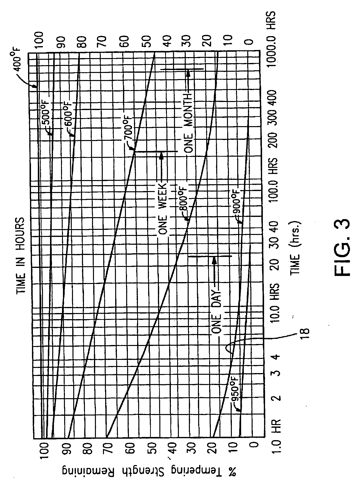
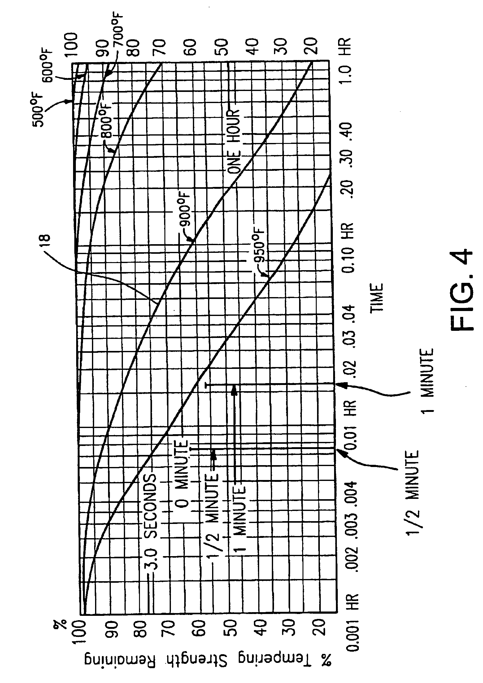
Such a significant loss (i.e., 80% loss) of temper strength is of course undesirable.
This may or may not be desirable in some instances.
Even when non-tempered glass substrates are used, the high temperatures applied to the entire VIG assembly may melt the glass or introduce stresses.
These stresses may increase the likelihood of deformation of the glass and/or br

Method used


Image

  • Vacuum insulating glass unit including infrared meltable glass frit, and/or method of making the same
  • Vacuum insulating glass unit including infrared meltable glass frit, and/or method of making the same
  • Vacuum insulating glass unit including infrared meltable glass frit, and/or method of making the same

Examples


Embodiment Construction

[0029]Certain embodiments of this invention relate to an improved peripheral or edge seal in a vacuum IG window unit, and / or a method of making the same. “Peripheral” and “edge” seals herein do not mean that the seals are located at the absolute periphery or edge of the unit, but instead mean that the seal is at least partially located at or near (e.g., within about two inches) an edge of at least one substrate of the unit. Likewise, “edge” as used herein is not limited to the absolute edge of a glass substrate but also may include an area at or near (e.g., within about two inches) of an absolute edge of the substrate(s). Also, it will be appreciated that as used herein the term “VIG assembly” refers to an intermediate product prior to the VIG's edges being sealed and evacuation of the recess including, for example, two parallel-spaced apart substrates and a frit. Also, while the frit may be said to be “on” or “supported” by one or more of the substrates herein, this does not mean t...


PUM

PropertyMeasurementUnit
Fractionaaaaaaaaaa
Fractionaaaaaaaaaa
Lengthaaaaaaaaaa

Abstract

Certain example embodiments of this invention relate to vacuum insulating glass (VIG) units including infrared meltable glass frits, and/or methods of making the same. More particularly, certain example embodiments relate to increasing the amount of ferrous oxide in glass frits (e.g., lead-free glass frits) used to form edge seals such that the glass frits absorb an increased amount of IR energy. The techniques of certain example embodiments make it possible to expose some or all of the VIG intermediate assembly to infrared source(s), since the glass frit will heat up faster than the substrates thereby reducing the likelihood of the first and/or second substrate melting and losing heat treatment strength. In certain example embodiments, the frit's glass redox (FeO/Fe2O3) preferably is at least about 0.02 higher than either (or the higher) of the substrates' glass redox (FeO/Fe2O3), more preferably at least about 0.04 higher, and most preferably at least about 0.06 higher.

Description

FIELD OF THE INVENTION[0001]Certain example embodiments of this invention relate to edge sealing techniques for vacuum insulating glass (VIG) units. More particularly, certain example embodiments of this invention relate to increasing the amount of ferrous oxide in glass frits (e.g., lead-free glass frits) used to form edge seals such that the glass frits absorb an increased amount of infrared radiation. Advantageously, the techniques of certain example embodiments enable the edge sealing process to be shortened from hours to minutes. The techniques of certain example embodiments additionally make it possible to expose some or all of the VIG intermediate assembly to the infrared source(s), since the glass frit will heat up faster than the substrates thereby reducing the likelihood of the first and / or second substrate melting and losing heat treatment (HT) strength (e.g., temper strength). In certain example embodiments, the frit's glass redox (FeO / Fe2O3) preferably is at least about...

Claims


Application Information

Patent Timeline
IPC IPC(8): C03B29/00C03C8/02B32B3/02
CPCE06B3/66304E06B3/66357E06B3/677C03C27/06E06B3/66333C03C17/04C03C8/24Y10T428/24777C03C8/02E06B2003/66338
Inventor WANG, YEI-PING (MIMI) H.
Owner GUARDIAN GLASS LLC
Why Eureka
Try Eureka