Eureka AIR delivers breakthrough ideas for toughest innovation challenges, trusted by R&D personnel around the world.

Magnetic Method and System for Locating A Target

a magnetometric and target technology, applied in the direction of diagnostics, gyroscopes/turn-sensitive devices, speed measurement using gyroscopic effects, etc., can solve the problem of not being able to use in certain procedures to provide real-time three-dimensional location information

Inactive Publication Date: 2010-11-04
TOPSHOOTER MEDICAL IMRI
View PDF4 Cites 45 Cited by
  • Summary
  • Abstract
  • Description
  • Claims
  • Application Information

AI Technical Summary

Benefits of technology

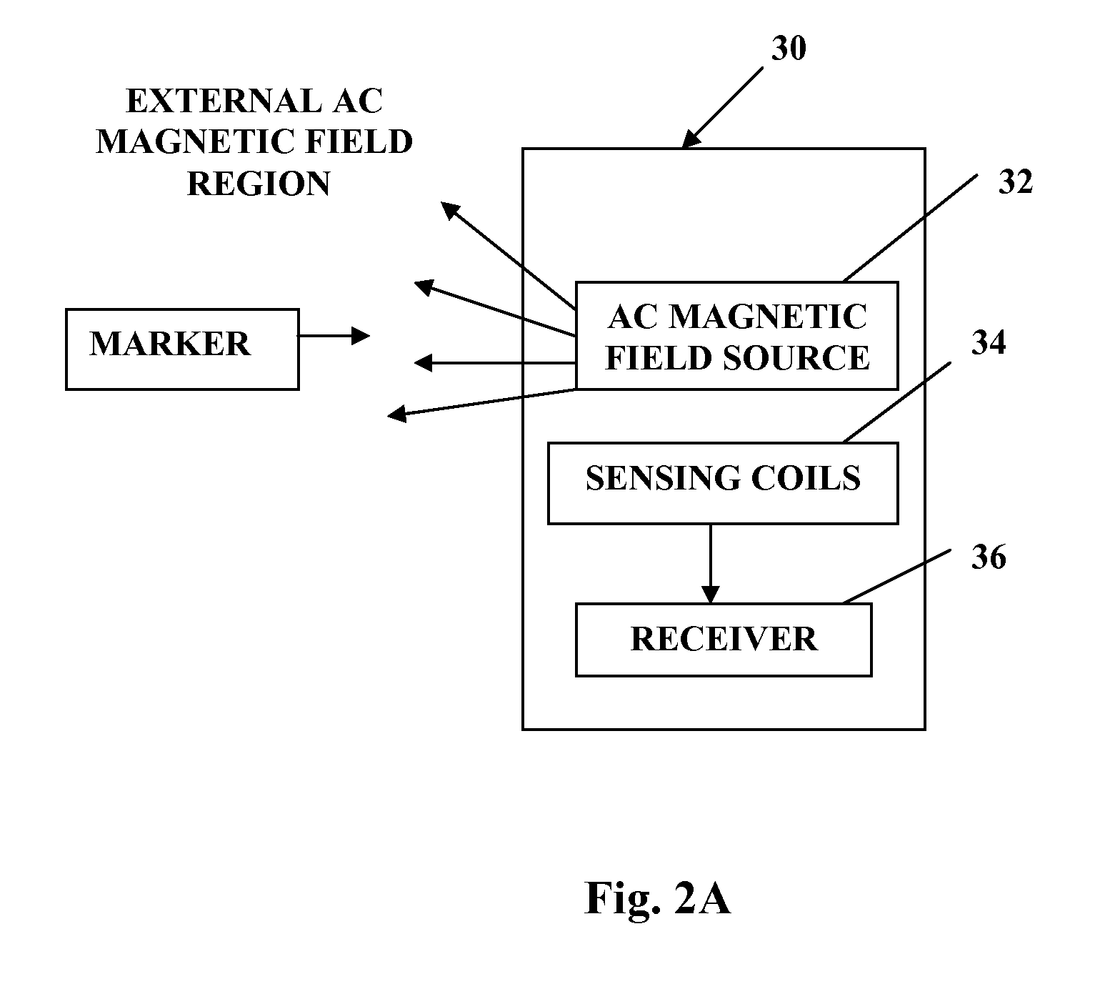
[0022]Preferably, the interaction between adjacent sensing coils within each array of the transceiver antenna system is minimized by associating each coil with its own amplifier. Also, preferably, the sensing aperture of the sensing coil is partially overlapping with that of an adjacent coil, setting their mutual inductance, and thus the coupling, to zero.
[0040]The detection system determines the marker location based on an interpolation of a set of calculated measurements from the sets of reference measurements of known locations near the closest known location. Thus, the detection system uses the set of reference measurements to find a known location that is close to the marker location to an accuracy that is dependent on the spacing of the known locations. The detection system then uses an interpolation of sets of reference measurements at known locations near the closest known location to more accurately identify the marker location at a location between the known locations.

Problems solved by technology

While the imaging systems can be very useful in some situations, they might be unusable or difficult to use in certain procedures to provide real time three dimensional location information about a target.

Method used


Image

  • Magnetic Method and System for Locating A Target
  • Magnetic Method and System for Locating A Target
  • Magnetic Method and System for Locating A Target

Examples


Embodiment Construction

[0079]While the invention is susceptible to various modifications and alternative forms, specific embodiments thereof have been shown by way of example in the drawings and will herein be described in detail. It should be understood, however, that it is not intended to limit the invention to the particular forms disclosed, but on the contrary, the intention is to cover all modifications, equivalents, and alternatives falling within the spirit and scope of the invention as defined by the appended claims.

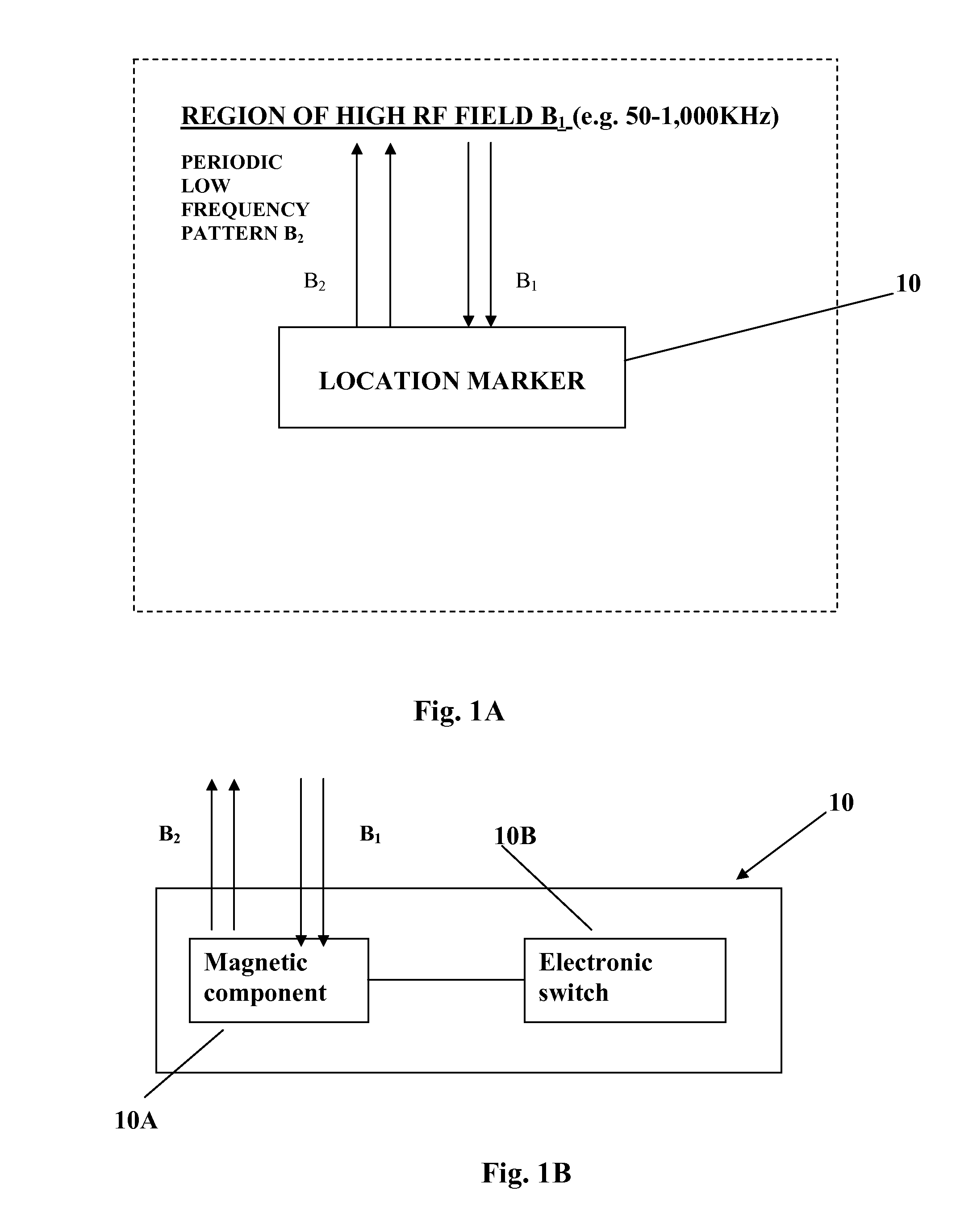
[0080]The present invention provides a novel location marker, a novel target location system and a novel antenna system. The concept of the present invention can be used in various article's identification and location applications, and is particularly useful in medical application for locating a target (e.g. a region inside a patient's body, or the distal end of a catheter or endoscope) by “marking” this location by means of associating the target location with the detectable location...


PUM


Abstract

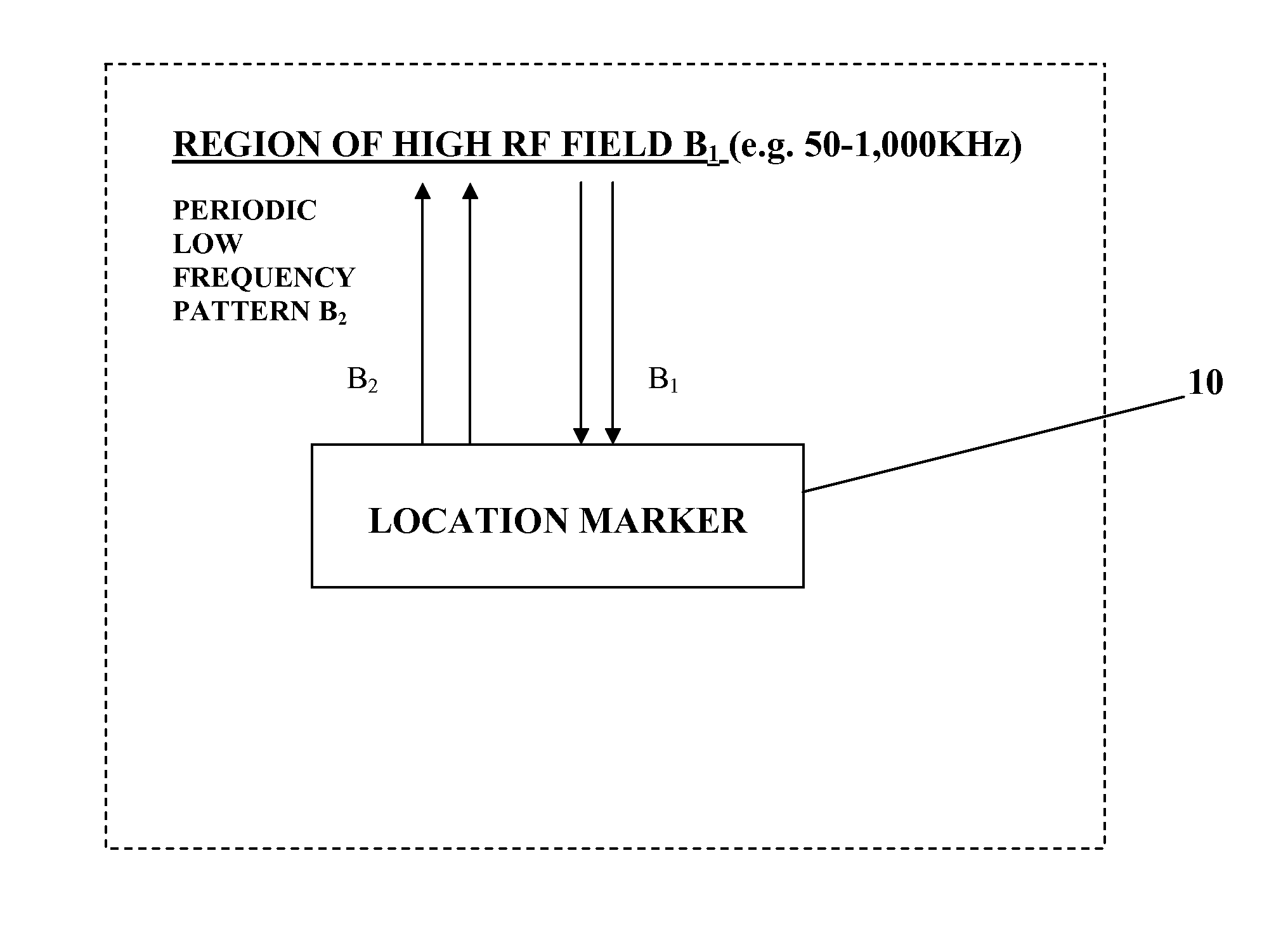
The present invention provides an accurate and real-time acquisition and monitoring of three-dimensional location information about a target, in particular a target inside a subject's body during a medical procedure. This is achieved in accordance with the invention by marking the target location by a small-size location marker, which can be detected and located with high signal-to-noise ratio of the detection by a detection system located at a distance from the target. Provided by the invention is a location marker, a target location system utilizing such marker, and also a novel antenna system suitable to be used in the target location system. The marker of the present invention is a passive electronic device, which “responds” to an external high radio frequency electromagnetic field by a periodic time pattern of a single (certain fixed value) relatively low frequency, as compared to the known devices of the kind specified emitting a frequency coded signal.

Description

FIELD OF THE INVENTION[0001]The present invention is in the field of magnetic techniques for target location and relates to various aspects involved in such techniques, including a marker, an antenna array and detection system.BACKGROUND OF THE INVENTION[0002]Techniques for identifying a target and determining the target location are used in various applications including inter alia security and medical applications. Conventional techniques of the kind specified typically utilize appropriate markers responding to an interrogating field.[0003]Medical procedures often require locating and treating areas within a subject's (patient's) body. Imaging systems, including X-ray, MRI, CT, and ultrasound have been used to assist in locating areas or particular targets within the body. While the imaging systems can be very useful in some situations, they might be unusable or difficult to use in certain procedures to provide real time three dimensional location information about a target.[0004]...

Claims


Application Information

Patent Timeline
Patent Type & Authority Applications(United States)
IPC IPC(8): A61B19/00G06F15/00G01B7/004H01H47/22
CPCA61B19/54G01D5/2066A61B2019/5475A61B90/39A61B2090/3975
Inventor KEREN, HANAN
Owner TOPSHOOTER MEDICAL IMRI
Why Eureka
Eureka Blog
Learn More