Optical probe

a technology of optical probes and probes, applied in the field of optical probes, can solve the problems of poor tracking resolution, poor accuracy, and inability to wear, brake or calibrate the optical probes, and achieve the effects of reducing processing power, low resolution, and low tracking resolution

Inactive Publication Date: 2010-11-04
ANTONIS JAN
View PDF20 Cites 0 Cited by
  • Summary
  • Abstract
  • Description
  • Claims
  • Application Information

AI Technical Summary

Benefits of technology

[0023]As a result of the camera and markers being of the visible light type, more image processing is required to extract the markers from the image in the measuring mode. To offset this, the digital camera can optionally operate in two modes, a low resolution video mode for real-time tracking of the optical probe and a very high resolution still mode for taking measurements. Advantageously, the exact location of the markers is only required in the still mode reducing the processing power during the low resolution tracking mode. A 16 MP camera creating 30 images of 24 bits per pixel would create 1.44 Gigabytes of information every second. Clearly this is a huge amount of data to transmit from the camera to the computer and then to process in the computer. If a lower tracking resolution is acceptable it is therefore advantageous to create an optical probe which is operable at 2 resolutions, a low resolution for tracking and a high resolution for single important measurements.
[0024]Therefore, the general location of the markers of the hand held device are already defined by the computer within the video tracking mode. On actuation of a trigger, a very high resolution still mode image is taken by the visible light camera for taking high accuracy measurements. The processing power required to identify the exact location of the markers in the high resolution image is greatly reduced by the fact that their general location has already been defined by the computer during the low resolution tracking mode. This significantly reduces the amount of the high resolution image which must be analyzed to initially determine the general location of the markers.
[0025]Preferably, the high resolution digital camera has a mechanical shutter. Advantageously, a physical shutter is used to expose the sensor during the acquisition of full resolution measurement images to eliminate the inaccuracies caused by tearing, blooming or smearing in the image.

Problems solved by technology

However, unlike a CMM arm, an optical probe has no mechanical mechanisms to wear, brake or calibrate.
While other optical probes do exist they suffer from a number of problems.
One group of prior art probes requires the use of expensive narrow spectrum cameras and markers.
If the image contains a lot of data other than the markers, a large amount of image processing is required to extract the markers.
These cameras and markers are much more specialized and consequently more expensive than traditional visible light cameras.
These systems also require the use of point light source markers and these point light source markers can introduce inaccuracy into the system.
However, point light sources can create systematic errors in their estimated location when they are either overexposed, moving, out of focus and affected by the inevitable perspective associated with any image.
As an optical probe is usually a hand held device, it cannot be considered a static device.
In the case of CCD sensors, this digital process is prone to blooming, smearing or overexposure during the imaging process, and in the case of CMOS sensors, this allows tearing of the image.
While both of these problems may be acceptable in a traditional imaging system, they introduce unwanted errors in the estimation of the markers location.

Method used


Image

  • Optical probe
  • Optical probe
  • Optical probe

Examples


Embodiment Construction

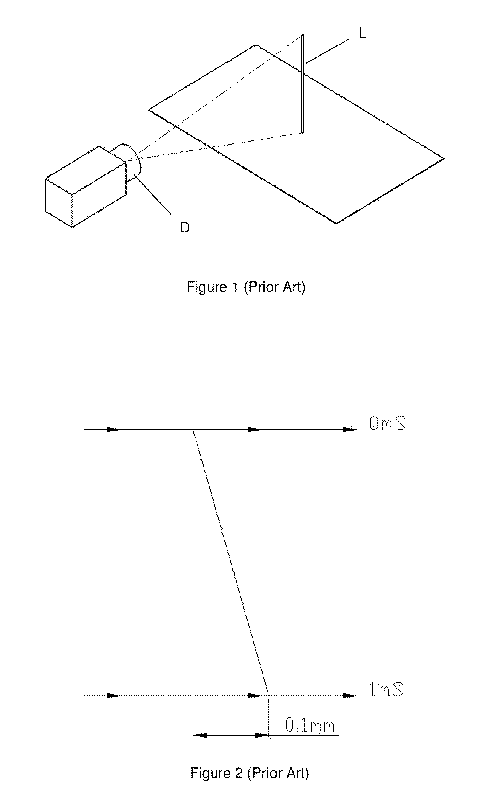
[0082]Referring initially to the prior art system shown in FIG. 1, where a high frequency digital image acquisition technique often referred to as an electronic shutter is used, a CMOS imaging chip is used in the digital camera D. As an optical probe is usually a hand held device, it cannot be considered a static device. If the optical probe moves at a speed of 100 mm / s, then it will move 0.1 mm in 1 millisecond, as illustrated in the digital image of FIG. 2 where the lamppost L of FIG. 1 appears diagonally because of the movement, and in the case of a CMOS sensor, this is known as tearing of the image. The accuracy of a typical CMM arm is less than 0.1 mm; therefore it is essential that the optical probe is imaged in as short a time as possible. In order to achieve this, prior art optical probes electronically read the digital camera sensor at a very high frequency. In the case of CCD sensors, this digital process is prone to blooming, smearing or overexposure during the imaging pr...


PUM


Abstract

An optical probe having a hand held device with markers, a digital camera for digitally imaging the handheld device with markers, and a computer for calculating the position of the hand held device from the position of the markers in the digital image. This allows the hand held device to be used to take measurements, wherein the digital camera is a high resolution visible light digital camera and the markers are visible light markers.

Description

CROSS-REFERENCE TO RELATED APPLICATION[0001]The instant application claims priority to United Kingdom Patent Application No. 0907394.1, filed Apr. 30, 2009, pending, the entire specification of which is expressly incorporated herein by reference.FIELD OF THE INVENTION[0002]The present invention relates to an optical probe and in particular to an optical probe for reducing the complexity of the apparatus and reducing the processing power required to take accurate measurements.BACKGROUND OF THE INVENTION[0003]An optical probe is a measuring device, which can be used like a traditional Coordinate Measuring Machine (CMM) arm supplied by manufacturers such as Faro or Romer. However, unlike a CMM arm, an optical probe has no mechanical mechanisms to wear, brake or calibrate. Instead, it consists of a hand held device with markers, a digital camera and a computer. The digital camera images the hand held device and its markers and a computer calculates the position of the hand held device f...

Claims


Application Information

Patent Timeline
Patent Type & Authority Applications(United States)
IPC IPC(8): H04N7/18
CPCG01B11/002
Inventor ANTONIS, JAN
Owner ANTONIS JAN
Why Eureka
Try Eureka