Method of fluorescence imaging

a fluorescence imaging and lifetime technology, applied in material analysis, instruments, computer peripheral equipment, etc., can solve the problems of inacceptable low light-level applications, slow and cumbersome passband transmission efficiency, and inability to achieve low-light-level applications, and achieve faster and more accurate data analysis. , good initial parameters

Active Publication Date: 2010-11-04
EURON COMMUNITY EC
View PDF7 Cites 11 Cited by
  • Summary
  • Abstract
  • Description
  • Claims
  • Application Information

AI Technical Summary

Benefits of technology

[0019]By this segmentation step, a priori information can be provided that will speed-up the fitting algorithms traditionally employed to determine fluorescence parameters by raster scanning. Indeed, as is well known in the art, the process of FLIM or HSI image analysis is usually performed by iterative fitting of the experimental data with mathematical models. The image segmentation and provision of expected fluorescence parameters permits to have a good initial parameters for the decay (for FLIM) or spectra (for HSI) fitting algorithms that are used to determine the parameters of the fluorescence signals acquired during raster scanning.
[0020]The present method thus significantly differs from conventional scanning FLIM where data analysis is performed off-line without any a priori information and thus using random initial parameters in the fitting algorithms. Moreover the proposed method supplies Good Initial Parameters for further faster and more accurate data analysis based on information gained from photo-physically similar regions, which could be called Local Analysis, in opposite to Global Analysis algorithms which average the fluorescence signal and loose details.
[0023]Preferably, the excitation light pattern generating device comprises a digital micromirror device (DMD). Such a spatial illuminator is compact and does not comprise any macro mechanical moving parts. The DMD can easily be controlled to reflect excitation light at any 2D area (region) on the sample to perform the localised fluorescence analysis of step c). In addition, the DMD can advantageously be controlled to generate a moving excitation light spot in order to perform the raster scanning of excitation light in step e), which is a kind of illumination pattern. Although a DMD is preferred for its ease of control, costs and reliability, one can use other spatial illuminators, e.g. a Liquid Crystal Transmittive or Reflective matrices. Steps c) and e) can even be performed with different devices.
[0031]In the case of fluorescence lifetime imaging, the present invention may be called segmented fluorescence lifetime imaging or “SFLIM”. Compared to traditional scan-type FLIM, it is of course not as precise but extremely faster. In the case of fluorescence spectra imaging, the present invention may be called segmented fluorescence hyper spectral imaging or “SHSI”. Compared to traditional scan-type HSI, it is of course not as precise but extremely faster.
[0035]The present methods will prove much faster and more accurate than conventional approaches in these techniques of FLIM and HSI, where there is typically no a priori information before raster scanning.

Problems solved by technology

This approach is straightforward and relatively cheap, but is usually rather slow and cumbersome due to the mechanical switching of the filters.
The LCTF solution offers approximately 30% of passband transmission efficiency, which is often unacceptable for low light-level applications.
While these parameters are good enough for static imaging, using a LCTF for HSI to study dynamic behavior in low-light level conditions can be problematic.
However, all these wide-field HSI systems based on tunable filters can suffer from relatively poor image quality due to the scattering present in most biological samples.
This can result in a decrease in image contrast and the loss of quantitative information, such as the concentration of a fluorophore.
However, since this approach usually requires raster scanning carried out by intricate electro-mechanical systems it is difficult and costly to implement.
The high cost and lack of portability are also issues, which have limited its uptake.
Still with respect to wide-field imaging, since the fluorescence information of the image-taken area is detected as a whole at the same time—problems of image blurring due to light scattering may arise.
Indeed, since the image pickup area is illuminated as a whole by a light source, detection and separation of weak fluorescence is difficult where there are multiple fluorescence spots around the weak point, because fluorescence light is scattered over the neighbourhood area, increasing background noise and overlapping the fluorescence to be measured.
Although a number of attractive commercial solutions exist based on both scanning methods, the disadvantages of point scanning in general are its low imaging rate and the lack of flexibility in how an image is formed.
Most scanning systems are analogue by nature and thus neither offer random access to any point or region of interest on the sample, nor the possibility to bin or combine the photons emitted from different locations.
An important issue in FLIM / HIS imaging is of course also the accuracy of data analysis.
By the extreme or complex nature of the phenomena observed the data analysis itself is also complex and time consuming.
Thus the fitting algorithm is extremely time consuming.
These methods suffer however either from loosing details (weak signal and its impact to the overall fluorescence is weak) or the need for high experience in manual marking the desired regions of interest and their use is limited to specific cases.

Method used


Image

  • Method of fluorescence imaging
  • Method of fluorescence imaging
  • Method of fluorescence imaging

Examples


Embodiment Construction

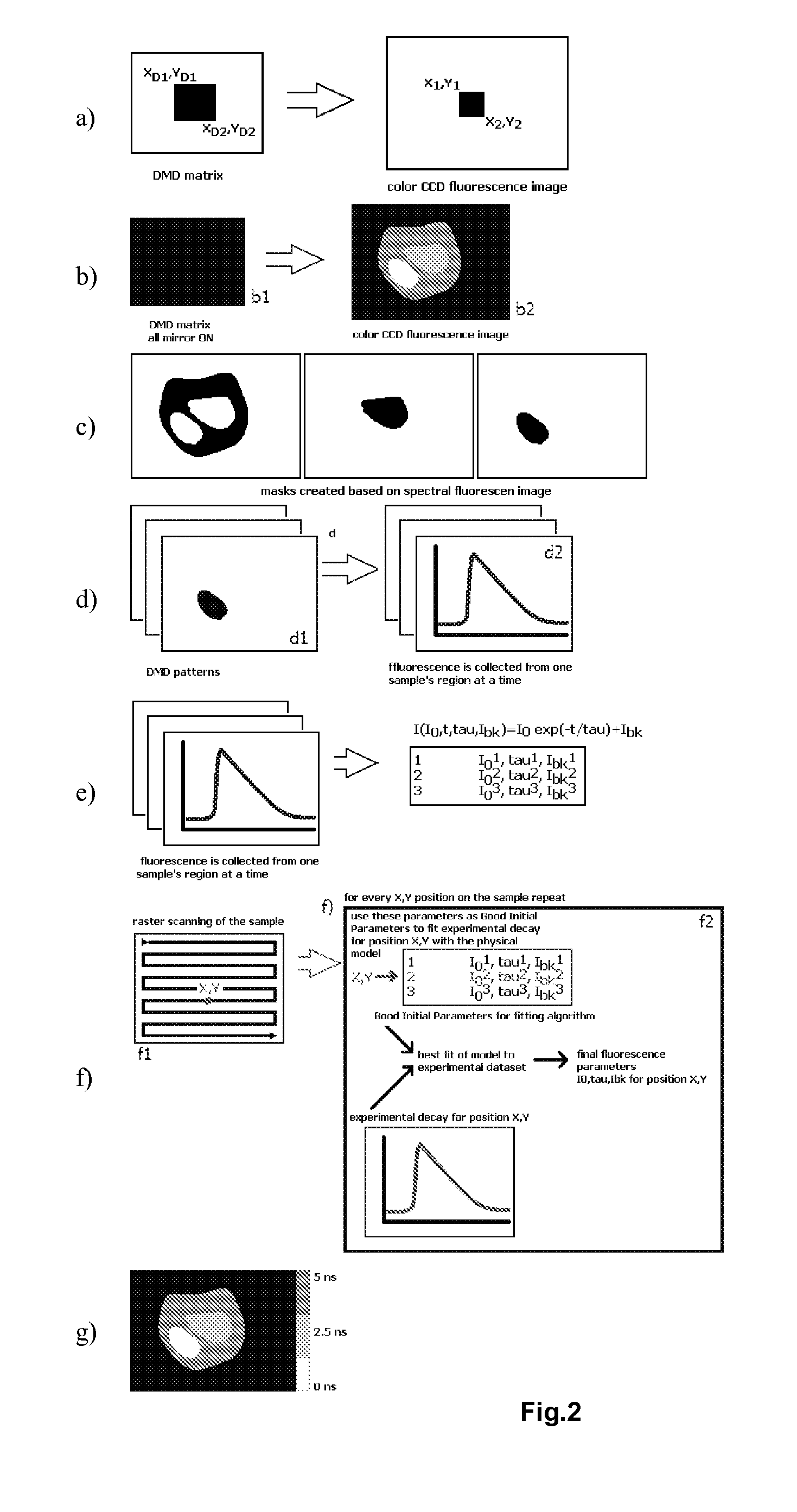
[0048]A preferred embodiment of the present method will now be described in more detail, as applied to raster-scanning FLIM with prior fluorescence image acquisition and analysis, in order to discriminate different structural and functional sample regions. The discrimination is performed by segmentation of a wide field fluorescence image (whole sample) based on fluorescence spectral and spatial information gained with any spectrally resolved imaging method. The goal of the method is to supply fluorescence decay fitting algorithms (in the case of FLIM) or fluorescence spectra fitting algorithms (in the case of HSI) with trained Good Initial Parameters to increase the accuracy and speed of FLIM / HSI image reconstruction.

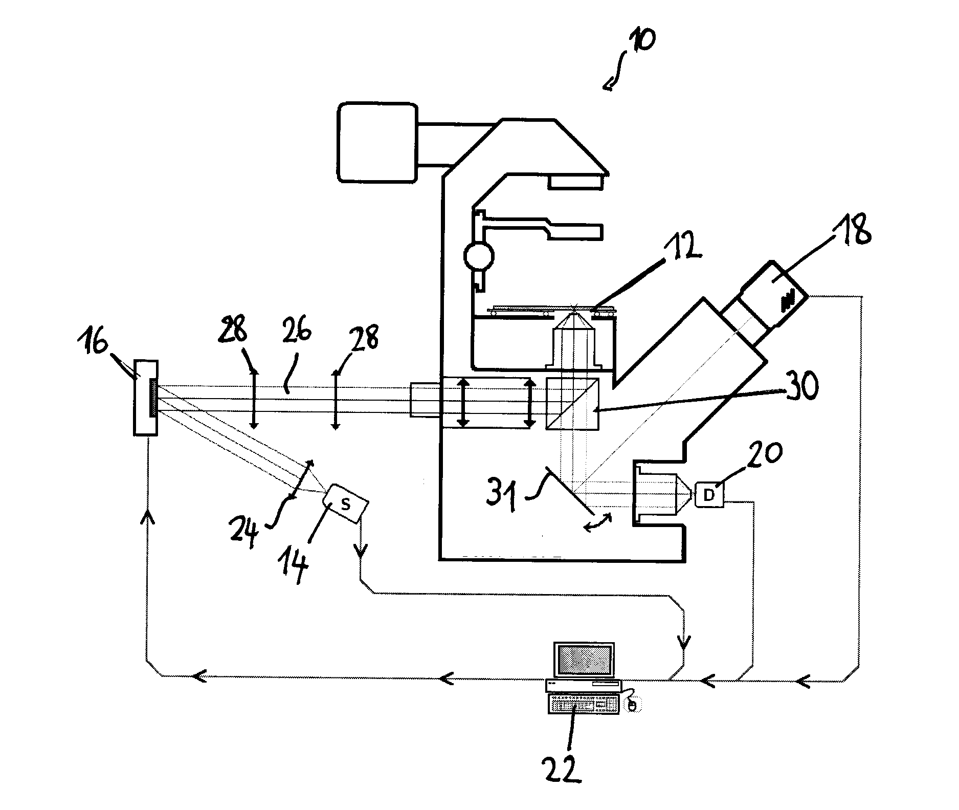
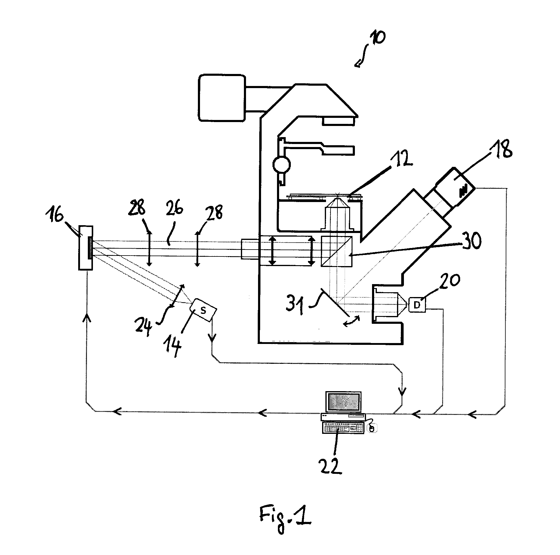
[0049]A preferred experimental setup for this method is illustrated in FIG. 1. It comprises e.g. microscope-type device 10 on which the sample to be analysed is supported on a stage, a light source 14 emitting excitation light—e.g. a pulsed laser diode (Pmax=1 mW, tFWHM...


PUM


Abstract

Method of fluorescence imaging including: illuminating a sample to excite its fluorescence and acquiring an image thereof; based on fluorescence spectral and spatial information from the sample's fluorescence image, segmenting the image into regions of similar spectral properties; for each image segment, exciting the fluorescence of the corresponding sample region, and detecting the corresponding fluorescence; based on modelling, determining expected fluorescence parameters from the fluorescence signals detected for each region; scanning the sample and determining final fluorescence parameters based on said expected fluorescence parameters.

Description

TECHNICAL FIELD[0001]The present invention generally relates to fluorescence imaging, and more particularly concerns fluorescence lifetime or spectrum imaging of biological samples.BACKGROUND ART[0002]Fluorescence imaging is a powerful technique for the analysis of biological samples. In the simplest case, an imaging system such as an epifluorescence microscope equipped with an excitation lamp and a filter-cube is used to illuminate the sample at one wavelength while imaging it at another.[0003]However, significantly more information can be obtained from the same sample if the more advanced techniques of Hyper-Spectral Imaging (HSI) or Fluorescence Lifetime Imaging (FLIM) are employed. In a HSI setup the complete fluorescence spectrum is acquired for every point of the object. It is a particularly useful method to clearly discriminate different structural features within a sample when multiple fluorescent dyes are employed whose spectra overlap (T. Zimmermann, “Spectral imaging and ...

Claims


Application Information

Patent Timeline
Patent Type & Authority Applications(United States)
IPC IPC(8): G06K9/00
CPCG01N21/00G01N21/6408G01N21/6458G02B21/365G01N2201/0675G02B21/16G01N2021/6423
Inventor BEDNARKIEWICZ, ARTURWHELAN, MAURICE
Owner EURON COMMUNITY EC
Why Eureka
Try Eureka