Test apparatus and method for safety valve

a technology for safety valves and apparatus, which is applied in the direction of functional valves, fluid tightness measurement, instruments, etc., can solve the problems of reducing the pressure of the reactor coolant system during operation, affecting the operation of the safety valve associated with the discharge of water from the loop seal, and parts of the safety valve may be damaged or loosened by vibration, etc., to achieve compact configuration, reduce installation space and material requirements, and facilitate production

Inactive Publication Date: 2010-11-11
KOREA HYDRO & NUCLEAR POWER CO LTD
View PDF2 Cites 29 Cited by
  • Summary
  • Abstract
  • Description
  • Claims
  • Application Information

AI Technical Summary

Benefits of technology

[0027]The testing apparatus performs tests under the same operation conditions (fluid, pressure and temperature) as a pressurizer safety valve installed on a reactor facility, so that it can perform the tests more precisely than an in-situ test using an auxiliary lift device and a bench test using a bench set on which the safety valve is mounted, both of which test under operation conditions different from those of the safety valve.
[0028]The testing apparatus includes an accumulator of an optimum volume having an electric heater of an optimum capacity and a test vessel of an optimum volume, which are required for testing the safety valve, so that it can relatively easily produce and use high-temperature, high-pressure steam required for testing the safety valve because a complicated boiler facility is not required.
[0029]The testing apparatus optimizes the size and capacity of main components, such as a water-supply treatment system, a water-supply pump, an accumulator, a test vessel and a condensing tank, on the respective quadrants as a closed loop so as to have a compact configuration, so that it can effectively reduce an installation space and materials required for manufacturing. Since the various components of the testing apparatus are located adjacent to each other when the testing apparatus is operated, it is very easy to observe the situations of the components or to monitor the instruments. As a result, this configuration is very effective for safe operation and optimum performance maintenance of the testing apparatus.
[0030]The testing apparatus is configured to sparge a large quantity of steam discharged when the subject safety valve is opened through a sparger submerged in the water of the condensing tank, and thus properly absorb energy generated from the safety valve, so that it can not only effectively reduce noise but also effectively condense and collect an expensive purified fluid.
[0031]Among the components of the testing apparatus, the accumulator can relatively easily produce high-temperature, high-pressure water and steam. Thus, the testing apparatus includes a blind flange capable of using the high-temperature, high-pressure water at a lower portion of the accumulator and another blind flange capable of using the high-temperature, high-pressure steam at an upper portion of the accumulator, so that it can perform various tests requiring the aforementioned high-temperature, high-pressure water and steam.

Problems solved by technology

When this test is performed, there is a possibility of causing a transient phenomenon in which the pressure of a reactor coolant system is reduced during operation, and a fluid containing radioactive materials is discharged through the safety valve.
When the safety valve is equipped with a loop seal, if the set pressure test is performed in the state in which loop seal water is drained, it is impossible to measure an influence of the operation of the safety valve associated with discharge of water from the loop seal.
In contrast, when the set pressure test is performed in the state in which loop seal water is not drained, parts of the safety valve may be damaged or loosened by vibration due to instantaneous discharge of water from the loop seal when the safety valve is operated.
Thus, there is a problem in that, in the event of overpressure of the facility or system (e.g. reactor coolant system), an actual opening pressure of the safety valve is not matched with the set pressure of the safety valve based on the bench test.
As such, the establishment of the safety valve test facility requires relatively high cost and wide space.
Further, when a discharge port of the subject safety valve is exposed to the air, excessive noise (e.g. of 130 dB or more) is generated.
Thus, it is difficult to install the test facility near a residential area.

Method used


Image

  • Test apparatus and method for safety valve
  • Test apparatus and method for safety valve
  • Test apparatus and method for safety valve

Examples


Embodiment Construction

[0038]Reference will now be made in greater detail to an exemplary embodiment of the present invention with reference to the accompanying drawings.

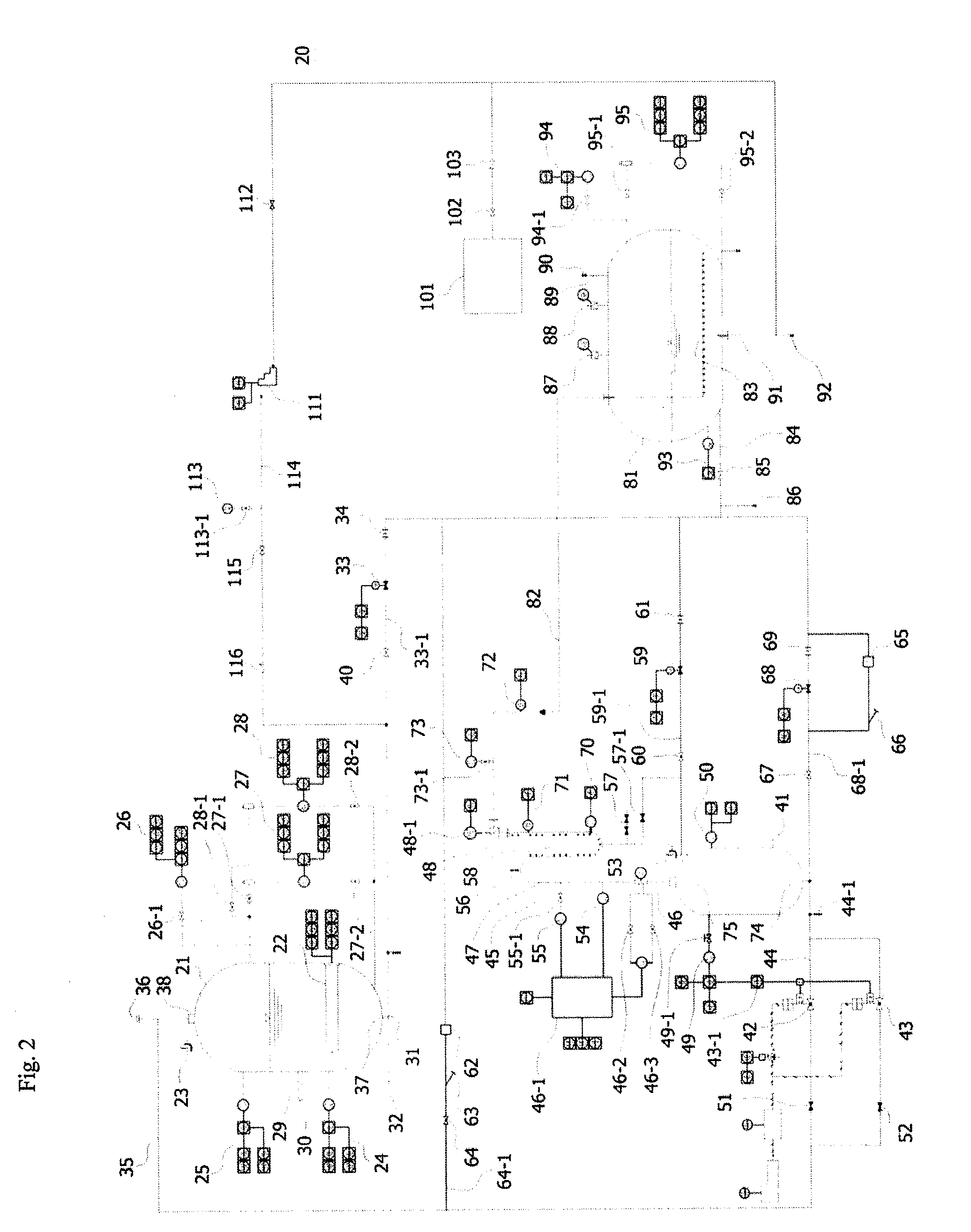
[0039]FIG. 2 is a piping and instrumentation drawing of an apparatus for testing the performance of a pressurizer safety valve according to an exemplary embodiment of the present invention.

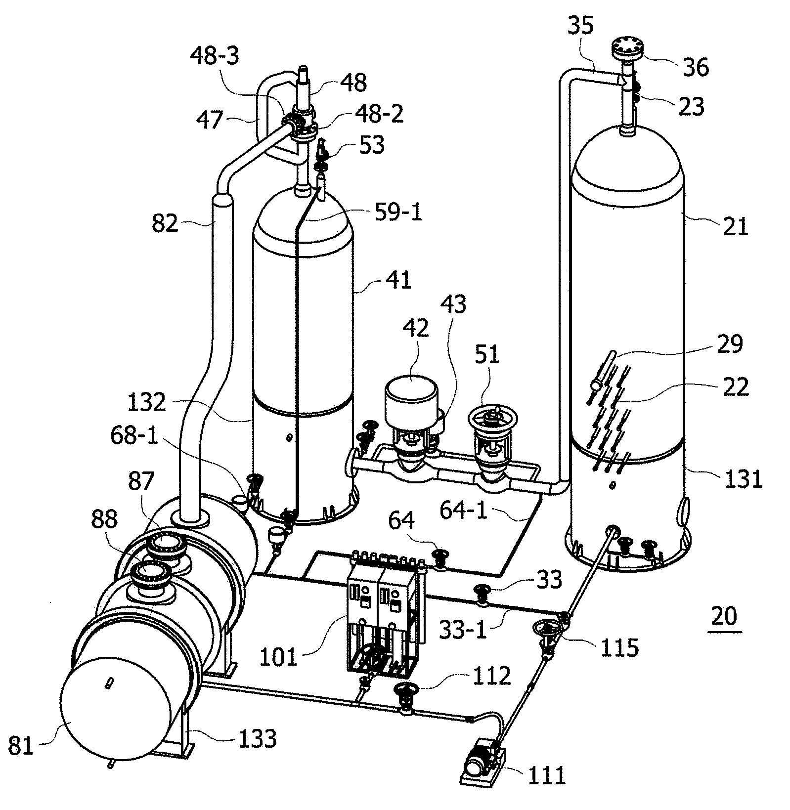
[0040]The testing apparatus 20 includes an accumulator 21, a test vessel 41, a condensing tank 81, a water-supply treatment system 101, a water-supply pump 111, pipes and valves, instruments, air compression systems, control and supervisory systems (not shown), and a power supply (not shown).

[0041]The accumulator 21 is a device that is filled with a predetermined amount of water, heats the water to produce steam using an electric heater, and stores high-pressure steam. The accumulator 21 is equipped with a plurality of electric heaters 22, each of which has a proper heat generation capacity (e.g. 300 kW) required to produce and pressurize the steam.

[004...


PUM


Abstract

An apparatus and method for testing the performance of a safety valve. The apparatus includes an accumulator including at least one electric heater for heating a predetermined amount of water in the accumulator, and storing steam produced by the electric heater, a test vessel storing the steam supplied from the accumulator, and providing steam at a test pressure to a safety valve, the steam being supplied after controlling flow rate and pressure, a condensing tank storing demineralized water to be supplied to the accumulator, and condensing and collecting the steam discharged from the safety valve, and a water-supply pump supplying the water stored in the condensing tank to the accumulator.

Description

TECHNICAL FIELD[0001]The present invention relates, in general, to an apparatus and method for testing the performance of a pressurizer safety valve installed on a reactor coolant system of a nuclear power plant, and more particularly, to an apparatus and method for testing the performance of a safety valve, which can perform a set pressure test, a seat tightness test, a flow rate test, a blow-down test, a water discharge test of a loop seal, a discharge load test, etc. on a pressurizer safety valve.BACKGROUND ART[0002]In general, a safety valve is a pressure relief device that is operated automatically by positive pressure on an inlet port side and is characterized by instantaneous opening. Such a safety valve typically has a built-in spring, and is opened or closed by force acting on this spring. This safety valve is used to prevent overpressure or to keep pressure constant in an apparatus that handles fluid.[0003]Particularly, a pressurizer safety valve used for a reactor coolant...

Claims


Application Information

Patent Timeline
Patent Type & Authority Applications(United States)
IPC IPC(8): G01M3/28G01M99/00
CPCG01M13/005F16K17/02G01M3/02G01M13/003G01M99/008Y10S251/00
Inventor OH, SEUNG-JONGJERNG, DONG-WOOKPARK, JONG-WOONKWON, KAB-JUKIM, CHANG-HYUN
Owner KOREA HYDRO & NUCLEAR POWER CO LTD
Why Eureka
Try Eureka