Control device for wind power systems having power failure detection

a technology of control device and wind power system, which is applied in the direction of process and machine control, electric generator control, instruments, etc., can solve the problems that the regulators would no longer be able to react sufficiently sensitively to the end of the grid dip, and achieve the effect of improving the dynamics of the regulator, improving the stability of the regulator, and being precis

Active Publication Date: 2010-11-11
SIEMENS GAMESA RENEWABLE ENERGY SERVICE GMBH
View PDF20 Cites 27 Cited by
  • Summary
  • Abstract
  • Description
  • Claims
  • Application Information

AI Technical Summary

Benefits of technology

[0015]It is particularly preferable for this to be an I-element which is initialized. The I-element is that component of the control unit which ensures steady-state accuracy. However, this is not entirely the case in the context of the invention but, on the contrary, the action on the I-element is used to improve the regulator dynamics. Surprisingly, by deliberately influencing the component for steady-state accuracy, specifically the I-element, the invention improves the dynamics, to be precise by greatly reducing the load on the drive train when the grid returns. Paradoxically, it is actually action on the I-element which ensures an improvement in the dynamic response.
[0016]This positive influence of the action on the I-element can be enhanced by the initializer furthermore varying a weighting factor of the component in the torque control unit. The initializer therefore does not just act on the component but also increases its weighting within the torque control unit. If the component is the I-element, this means that its weighting factor is varied, preferably increased. In one development, the initializer can vary at least one further weighting factor of another component. By way of example, this may be a P-element of a PI-regulator or an equivalent functional unit in some other control concept. This weighting factor is preferably varied in the opposite sense to the variation of the weighting factor in the I-element. The weighting factors are expediently not varied in the long term, but temporarily over an adjustable time period. This allows the variation of the weighting factors to be limited to the time period which is required for the oscillations in the drive train to decay.

Problems solved by technology

The regulators would then no longer be able to react sufficiently sensitively to the end of the grid dip.

Method used


Image

  • Control device for wind power systems having power failure detection
  • Control device for wind power systems having power failure detection
  • Control device for wind power systems having power failure detection

Examples


Embodiment Construction

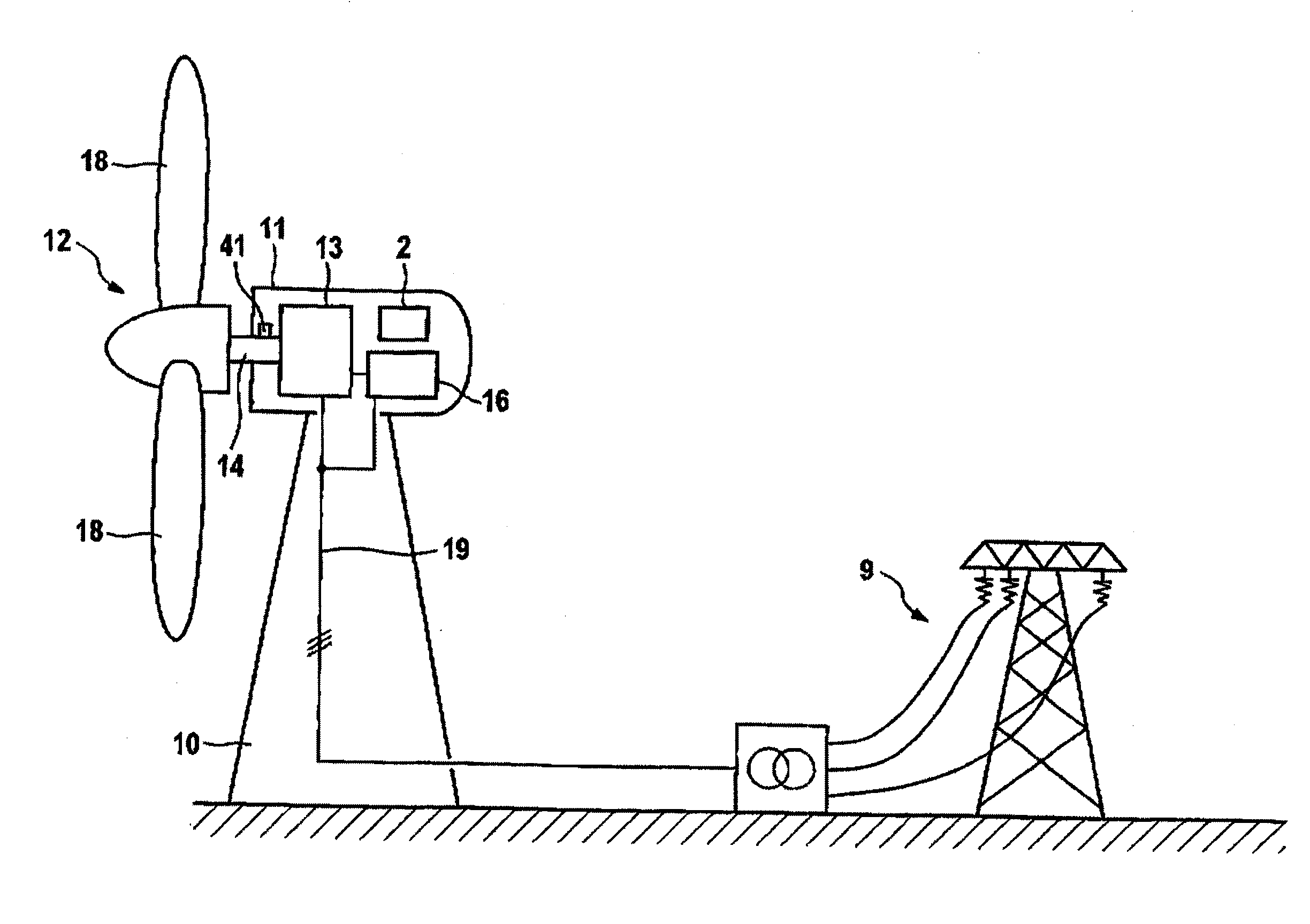
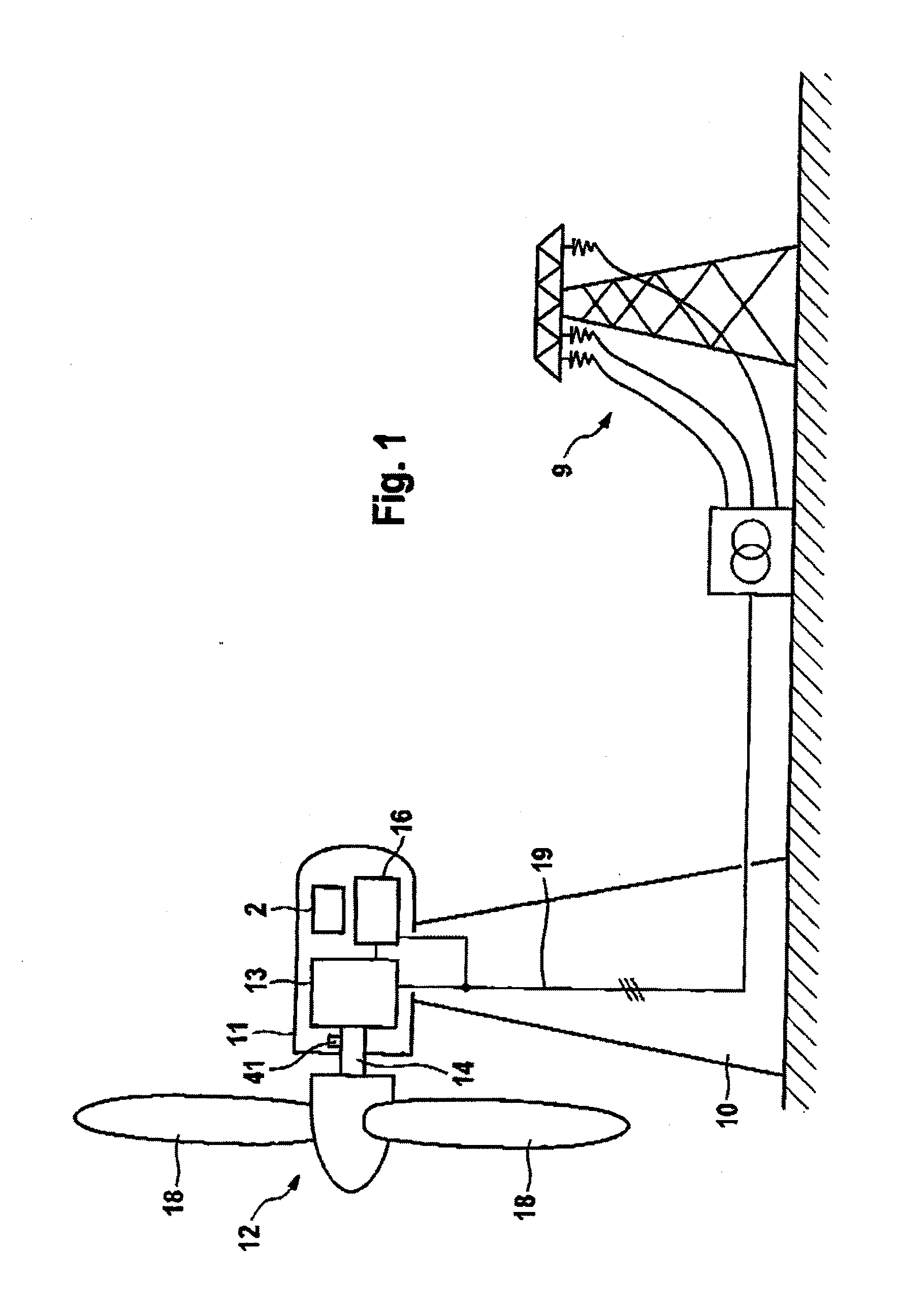
[0030]FIG. 1 illustrates a wind energy installation which is designed to implement the invention and is annotated in its totality with the reference number 1. In a manner known per se, this wind energy installation has a pod 11 which is arranged on a tower 10 such that it can swivel in the azimuth direction. A wind rotor 12 is arranged such that it can rotate on the end face of the pod 11 and, via a rotor shaft 14, drives a generator 13 which is preferably in the form of a double-fed asynchronous machine with rotor and stator winding having a number of winding sections. The stator winding of the generator 13 is connected directly to a connecting line 19 of the wind energy installation 1. The rotor winding (not illustrated) is likewise connected via a converter 16, to the connecting line 19. Furthermore, an operating control system 2 is provided, and is preferably arranged in the pod 11.

[0031]During normal operation, the mechanical power (wind power) extracted from the wind by the wi...


PUM


Abstract

A wind energy installation control device includes a wind rotor, a generator driven by the wind rotor, a torque control unit configured to control a torque of the generator, and a control system. The control system includes a detector configured to identify a grid dip and an end of the grid dip, a residual torque transmitter configured to provide a preset value for a torque of the generator after identification of the grid dip, and an initializer configured to initialize a component of the torque control unit at the preset value. Accordingly, upon return of grid power after a grid dip, the vibration behaviour of a wind power system can be significantly improved. Overload of a drive train upon return of grid voltage can thus be reduced.

Description

REFERENCE TO RELATED APPLICATIONS[0001]This application is a national stage application under 35 USC 371 of International Application No. PCT / EP2008 / 010312, filed Dec. 4, 2008, which claims the priority of German Patent Application No. 10 2007 060 958.4, filed Dec. 14, 2007, the contents of which prior applications are incorporated herein by reference.FIELD OF THE INVENTION[0002]The invention relates to a control device for wind energy installations having a wind rotor, a generator driven by the wind rotor, and a torque control unit for controlling the torque of the generator.BACKGROUND OF THE INVENTION[0003]Virtually all modern wind energy installations are de-signed for a variable rotation speed. This means that the wind rotor, which generally drives the generator via a transmission, can be operated at a different speed, depending on the wind conditions. To this end, a capability is provided to vary the pitch angles of the rotor blades of the wind rotor. Varying the pitch angle va...

Claims


Application Information

Patent Timeline
Patent Type & Authority Applications(United States)
IPC IPC(8): H02P9/04
CPCF03D7/0272F03D7/0284F03D7/043F03D9/003F05B2270/1071H02P2101/15F05B2270/706H02P9/02H02P9/102Y02E10/723F05B2270/10711F03D9/255F03D15/20Y02E10/72
Inventor KRUEGER, THOMAS
Owner SIEMENS GAMESA RENEWABLE ENERGY SERVICE GMBH
Why Eureka
Try Eureka