
Non-Linear Transformations for Enhancement of Images

a non-linear transformation and enhancement technology, applied in image enhancement, color signal processing circuits, instruments, etc., can solve the problems that the psf of the resulting optical system may still vary from the ideal, and achieve enhanced quality, enhanced electronic images, and reduced blur

Active Publication Date: 2010-11-11
DIGITALOPTICS CORPORATION
View PDF13 Cites 20 Cited by
  • Summary
  • Abstract
  • Description
  • Claims
  • Application Information

AI Technical Summary

Benefits of technology

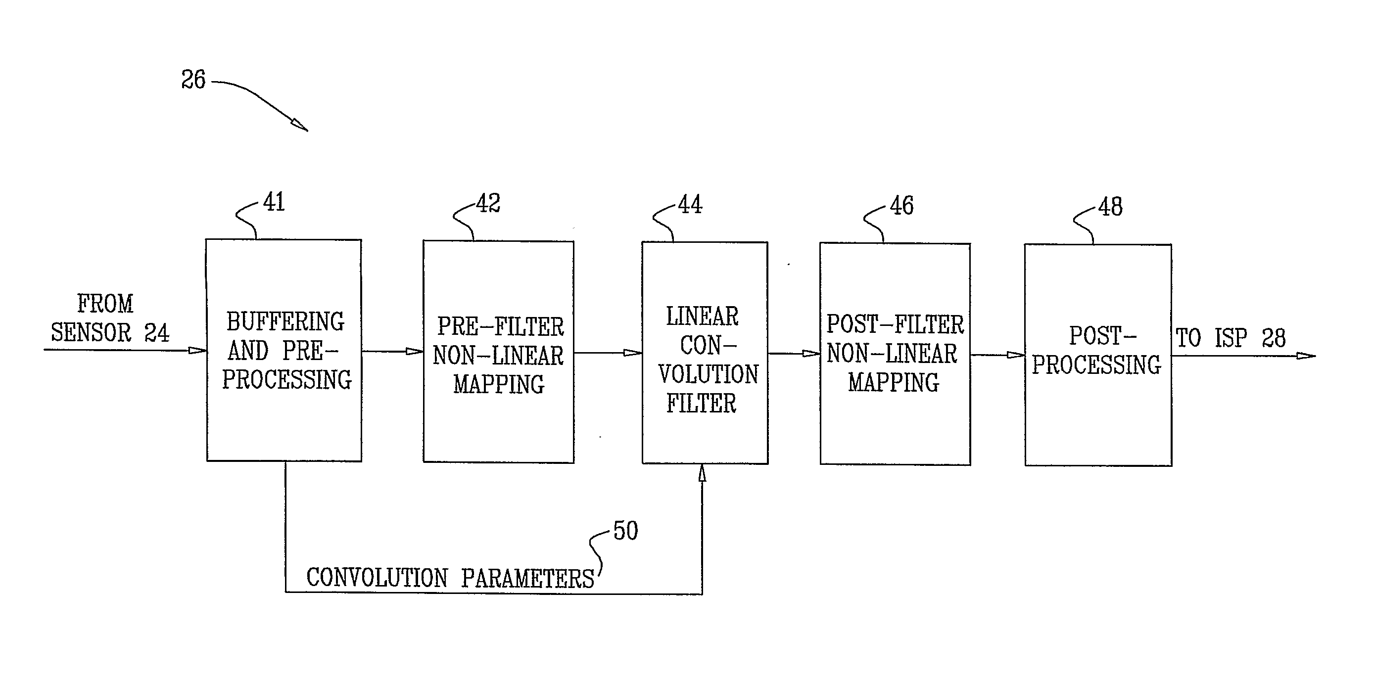
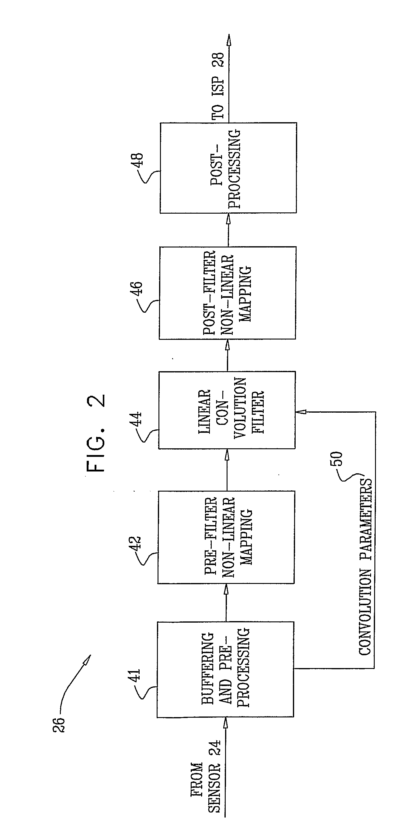
[0013]Embodiments of the present invention provide methods and devices for processing and enhancement of electronic images. An image sensor outputs a stream of input pixels values which suffer from an input blur. An image restoration circuit performs a non-linear mapping of the input pixel values to generate a mapped stream of output pixel values, and performs linear convolution filtering of the mapped stream of output pixel values to generate a filtered pixel stream with enhanced quality, such as with reduced blur. Typically, the images are produced using objective optics characterized by a point spread function (P SF) that causes the input blur, and the image restoration circuit includes a deconvolution filter (DCF), having a filter kernel determined according to the PSF.
[0014]The non-linear mapping typically spreads a portion of the input pixels with relatively low values over a larger range of output values, and contracts a portion of the input pixels with relatively high-amplitude values to a narrower range of output values. The mapping thus minimizes artifacts in the output pixel stream near low-illumination pixels. In some embodiments, the image restoration circuit performs a second non-linear mapping, generally inverse to the initial non-linear mapping, on the filtered pixel stream, in order to cancel a distortion of the input pixels caused by the initial non-linear mapping.
[0015]In some embodiments of the present invention, the image restoration circuit performs the non-linear mapping using a piecewise linear function. Alternatively or additionally, the image restoration circuit uses one or more look-up tables to approximate a continuous non-linear function, in order to mitigate any distortion in the output pixel stream that might otherwise be caused by sharp angles between segments of the piecewise linear function.
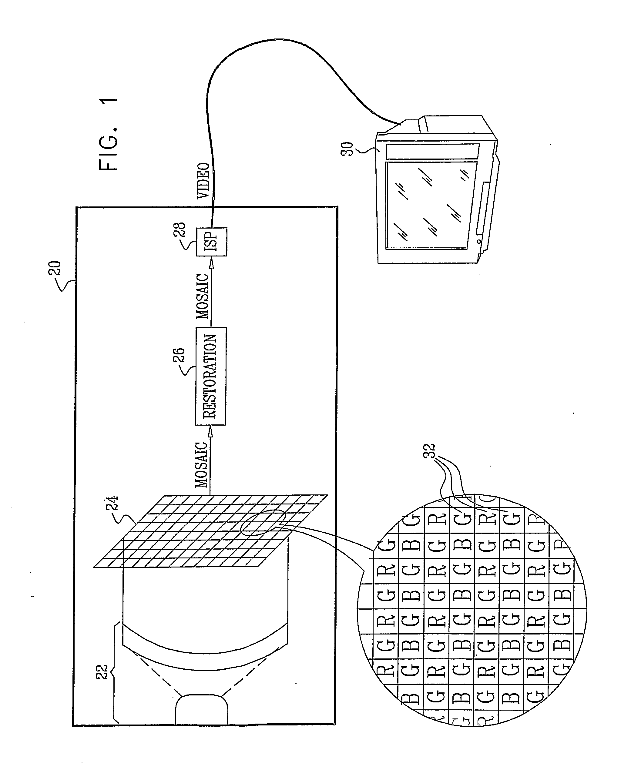
[0016]In some embodiments of the present invention, the image sensor comprises a mosaic image sensor, which outputs a stream of pixel values belonging to a plurality of input sub-images, each of which is due to light of a different, respective color that is incident on the mosaic image sensor. Following the non-linear mapping and linear convolution filtering, which generate corresponding output sub-images with enhanced quality, such as with reduced blur, an image signal processor (ISP) combines the output sub-images so as to generate a color video output image.

Problems solved by technology

The PSF of the resulting optical system may still vary from the ideal due to focal variations and aberrations.

Method used


Image

  • Non-Linear Transformations for Enhancement of Images
  • Non-Linear Transformations for Enhancement of Images
  • Non-Linear Transformations for Enhancement of Images

Examples


Embodiment Construction

[0048]FIG. 1 is a block diagram that schematically illustrates an electronic imaging camera 20, in accordance with an embodiment of the present invention. This specific, simplified camera design is shown here by way of example, in order to clarify and concretize the principles of the present invention. These principles, however, are not limited to this design, but may rather be applied in reducing the blur in images in imaging systems of other types, for example, in which a sensor produces multiple sub-images of different colors, which are then combined to produce an enhanced color output image.

[0049]In an embodiment of the present invention, in camera 20, objective optics 22 focus light from a scene onto a mosaic image sensor 24. Objective optics 22 is characterized by a point spread function (PSF) that gives rise to an input blur in the received image. Any suitable type of image sensor, such as a CCD or CMOS image sensor, may be used in the camera. In this example, as well as in t...


PUM


Abstract

Imaging apparatus (26) is provided for use with an image sensor (24). The apparatus includes a non-linear mapping circuit (42), which is configured to receive a raw stream of input pixel values generated by the image sensor and to perform a non-linear mapping of the input pixel values. to generate a mapped stream of mapped pixel values, and a linear convolution filter (44), which is arranged to filter the mapped stream of mapped pixel values to generate a filtered stream of filtered pixel values. Other embodiments are also described.

Description

CROSS-REFERENCE TO RELATED APPLICATIONS[0001]The present application claims the benefit of the following US provisional applications, both of which are assigned to the assignee of the present application and are incorporated herein by reference:[0002]U.S. Provisional Application 60 / 933,446, filed Jun. 5, 2007; and[0003]U.S. Provisional Application 61 / 072,132, filed Mar. 26, 2008.FIELD OF THE INVENTION[0004]The present invention relates generally to digital image processing, and specifically to methods and devices for enhancing image quality in digital cameras.BACKGROUND OF THE INVENTION[0005]The objective optics used in digital cameras are typically designed so as to minimize the optical point spread function (PSF) and maximize the modulation transfer function (MTF), subject to the limitations of size, cost, aperture size, and other factors imposed by the camera manufacturer. The PSF of the resulting optical system may still vary from the ideal due to focal variations and aberration...

Claims


Application Information

Patent Timeline
Patent Type & Authority Applications(United States)
IPC IPC(8): H04N9/04H04N5/217G06K9/40G06T5/00
CPCG06T5/003G06T5/008G06T2207/20012G06T2207/10024G06T5/20G06T5/94G06T5/73
Inventor KINROT, URI
Owner DIGITALOPTICS CORPORATION
Learn More