Systems and Techniques for Suppressing Backward Lasing in High-Power Cascaded Raman Fiber Lasers

a cascaded raman fiber laser, high-power technology, applied in the direction of laser details, active medium shape and construction, basic electric elements, etc., can solve problems such as component failure, and achieve the effects of preventing light power buildup, low loss, and high loss

Inactive Publication Date: 2010-11-11
OFS FITEL LLC
View PDF21 Cites 18 Cited by
  • Summary
  • Abstract
  • Description
  • Claims
  • Application Information

AI Technical Summary

Benefits of technology

[0010]According to one practice of the invention, a pump source provides pump power at a source wavelength. The pump power is launched as an input into a cascaded Raman resonator. A wavelength-dependent loss element is connected such that it precedes the cascaded Raman resonator. The wavelength-dependent loss element is configured to transmit light power at the source wavelength with low loss, and to provide high loss at the first Stokes shift. The wavelength-dependent loss element prevents buildup of light power between the pump source and the cascaded Raman resonator, thereby preventing backward propagation of light power back into the pump source.

Problems solved by technology

Ultimately, it can cause pulsing of the laser which can lead to component failure.

Method used


Image

  • Systems and Techniques for Suppressing Backward Lasing in High-Power Cascaded Raman Fiber Lasers
  • Systems and Techniques for Suppressing Backward Lasing in High-Power Cascaded Raman Fiber Lasers
  • Systems and Techniques for Suppressing Backward Lasing in High-Power Cascaded Raman Fiber Lasers

Examples


Embodiment Construction

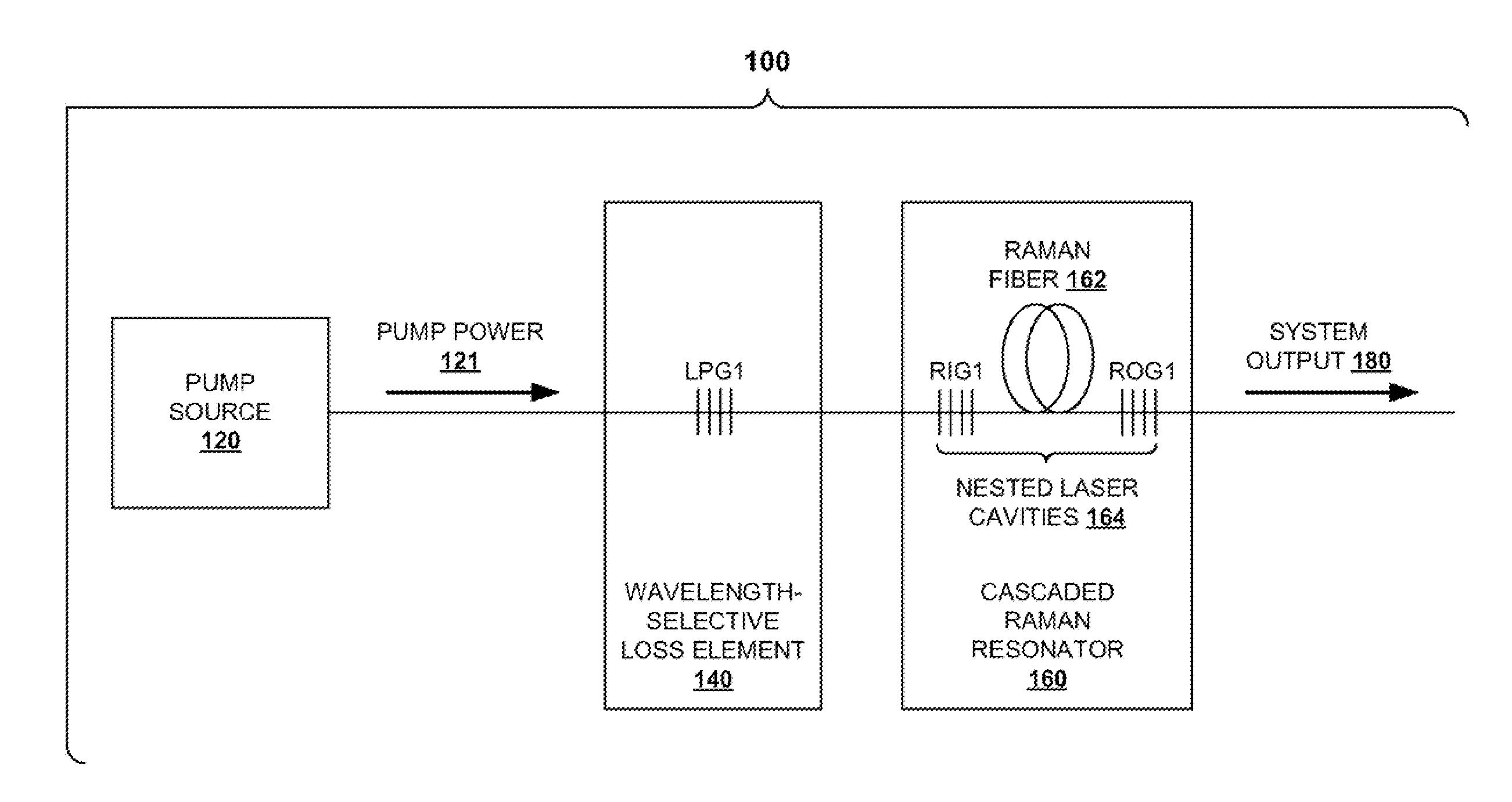
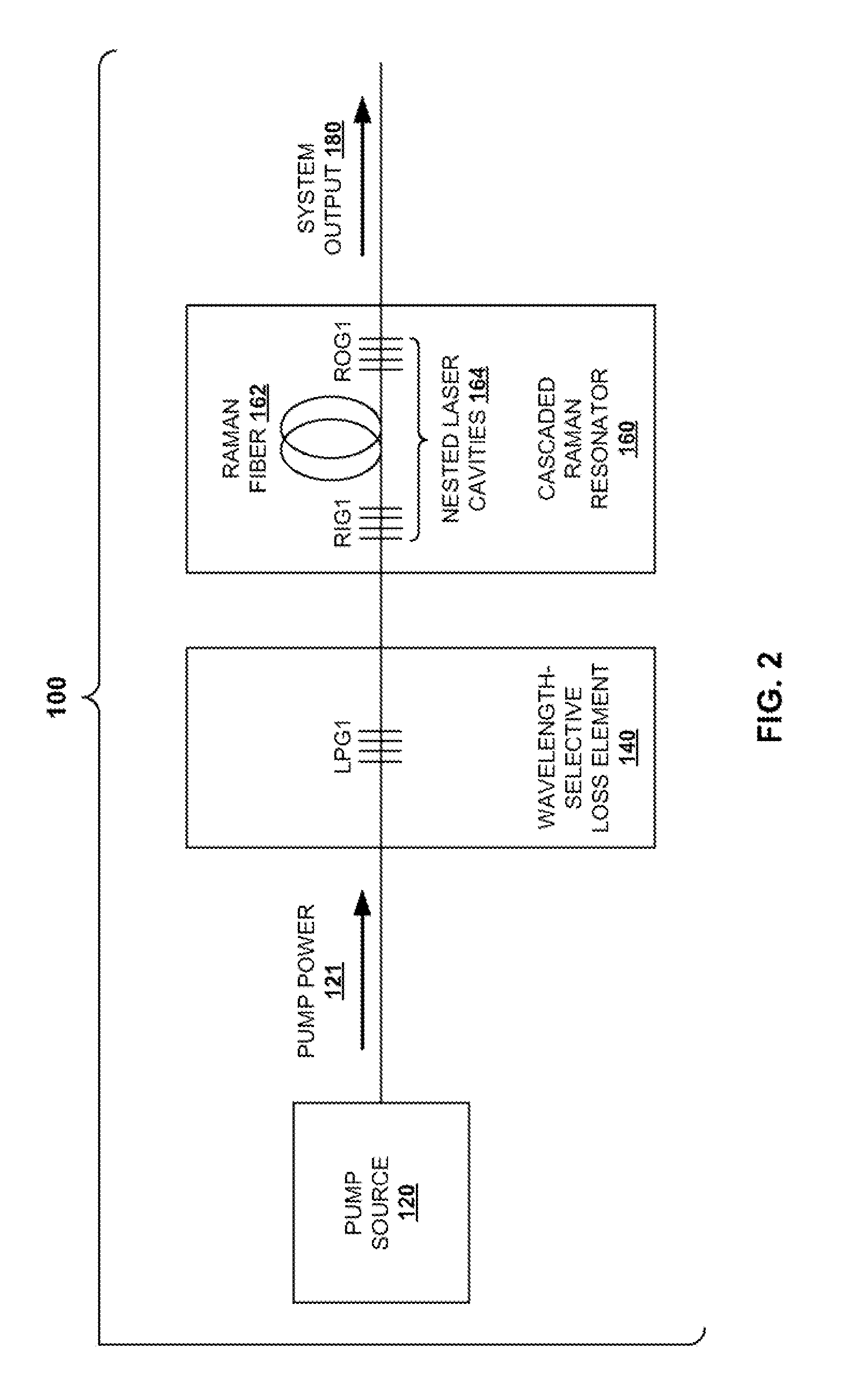
[0024]An aspect of the invention provides systems and techniques for suppressing backward lasing in high-power cascaded Raman fiber lasers. As described herein, suppression of backward lasing is accomplished by identifying signatures that point to the onset of backward lasing. The identification of these signatures is a very powerful technique. The temporal disturbances caused by backward lasing can lead to pulsing, which can destroy components at higher powers.

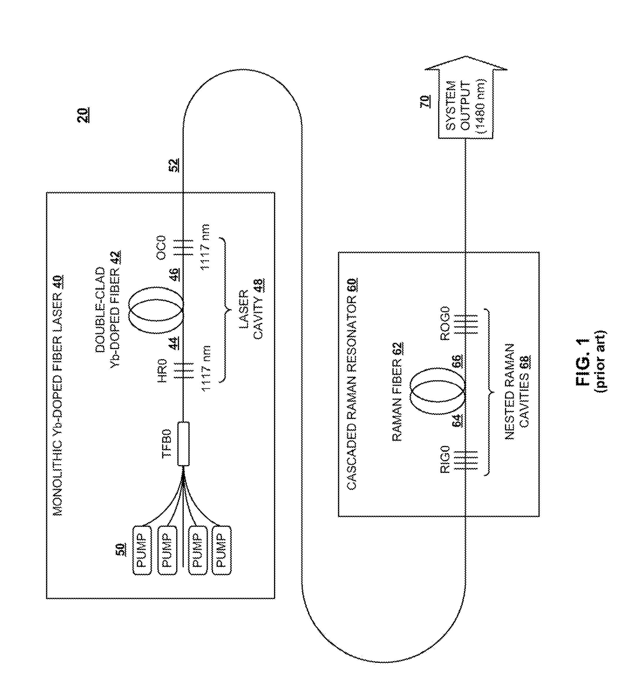
[0025]A further aspect of the invention provides a Raman lasing system in which a wavelength-dependent loss element is used to eliminate backward lasing from a cascaded Raman resonator by frustrating the buildup of radiation at the first Stokes shift. When a system according to the prior art, such as the FIG. 1 system discussed above, is operated at higher powers, this radiation building and backward lasing may result in failure, for example, of the pump laser high reflector (HR) when external devices are connected. According...


PUM


Abstract

In a light amplification system and technique, a pump source provides pump power at a source wavelength. The pump power is launched as an input into a cascaded Raman resonator. A wavelength-dependent loss element is connected such that it precedes the cascaded Raman resonator. The wavelength-dependent loss element is configured to transmit light power at the source wavelength with low loss, and to provide high loss at the first Stokes shift. The wavelength-dependent loss element prevents buildup of light power between the pump source and the cascaded Raman resonator, thereby preventing backward propagation of light power back into the pump source.

Description

CROSS REFERENCE TO RELATED APPLICATION[0001]The present application claims the priority benefit of United States Provisional Patent Application Ser. No. 61 / 177,058, filed on May 11, 2009, which is owned by the assignee of the present application, and which is incorporated herein by reference in its entirety.BACKGROUND OF THE INVENTION[0002]1. Field of the Invention[0003]The present invention relates generally to optical fiber devices and methods, and in particular to improved systems and techniques for suppressing backward lasing in high-power cascaded Raman fiber lasers.[0004]2. Background Art[0005]Stimulated Raman scattering in optical fibers is a useful effect that can be used to provide nonlinear gain at wavelength regions where rare-earth doped fibers do not operate. A cladding-pumped, Yb-doped fiber can serve as a brightness converter to convert high-power multi-mode diodes at 915 nm or 975 nm to single-mode radiation in the region of 1.0 to 1.2 micrometers. This can then be u...

Claims


Application Information

Patent Timeline
Patent Type & Authority Applications(United States)
IPC IPC(8): H01S3/30
CPCH01S3/0064H01S3/2375H01S3/0675H01S3/06754H01S3/06758H01S3/07H01S3/08086H01S3/094007H01S3/094042H01S3/09408H01S3/094084H01S3/09415H01S3/1618H01S3/302H01S3/06708H01S3/06733H01S3/094046H01S3/1608H01S3/0078
Inventor NICHOLSON, JEFFREY W.
Owner OFS FITEL LLC
Why Eureka
Try Eureka