Individual blade noise measurement system and method for wind turbines

a wind turbine and individual technology, applied in wind energy generation, amplifier modifications to reduce noise influence, liquid fuel engine components, etc., can solve the problems of long and costly steps in configuring wind turbine blade noise levels, rigging of wind turbine blades may require lifting equipment, personnel and time, etc., to reduce the preparation of blades, the effect of reducing time and cos

Active Publication Date: 2010-11-11
GENERAL ELECTRIC CO
View PDF3 Cites 10 Cited by
  • Summary
  • Abstract
  • Description
  • Claims
  • Application Information

AI Technical Summary

Benefits of technology

[0009]Advantages to an embodiment of the disclosure include the ability for different noise reduction measures to be tested simultaneously at one turbine. In addition, the noise measurement and analysis procedure permit the determination of individual noise level and noise level spectra of wind turbine blades.
[0010]The ability to measure noise level at individual blades allows time and cost reduction due to fewer measurements, crane actions and reduced blade preparation. Furthermore, the method of the present disclosure has lower uncertainty and greater noise level measurement detail than standard International Standard measurements.
[0011]The method also allows consistent and reliable noise level measurements at various dissimilar locations substantially independent of the environmental and site conditions.

Problems solved by technology

As the blades are rotated by the wind, noise is inherently generated.
Configuring of wind turbine blades for noise levels requires long and costly steps including outfitting of the blades, evaluating the blade set over a testing period wherein the process is then repeated for new blade arrangement.
The rigging of these blades may require lifting equipment, personnel and time.
Wind turbine blades and associated equipment may be large or heavy, requiring specialized equipment that is expensive to operate.
The installation, servicing and configuration may be very expensive and time consuming.

Method used


Image

  • Individual blade noise measurement system and method for wind turbines
  • Individual blade noise measurement system and method for wind turbines
  • Individual blade noise measurement system and method for wind turbines

Examples


Embodiment Construction

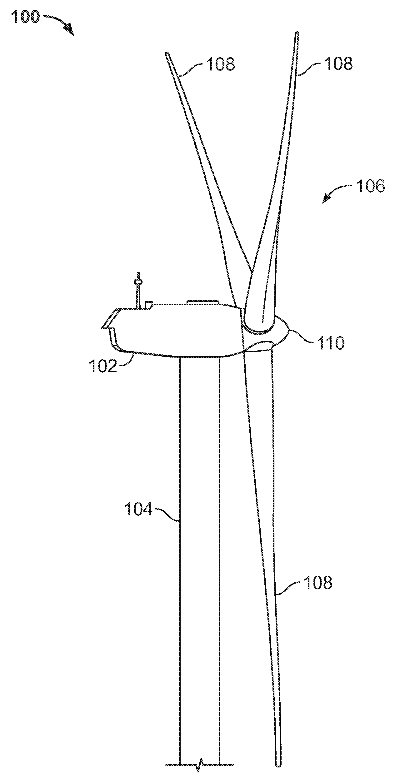
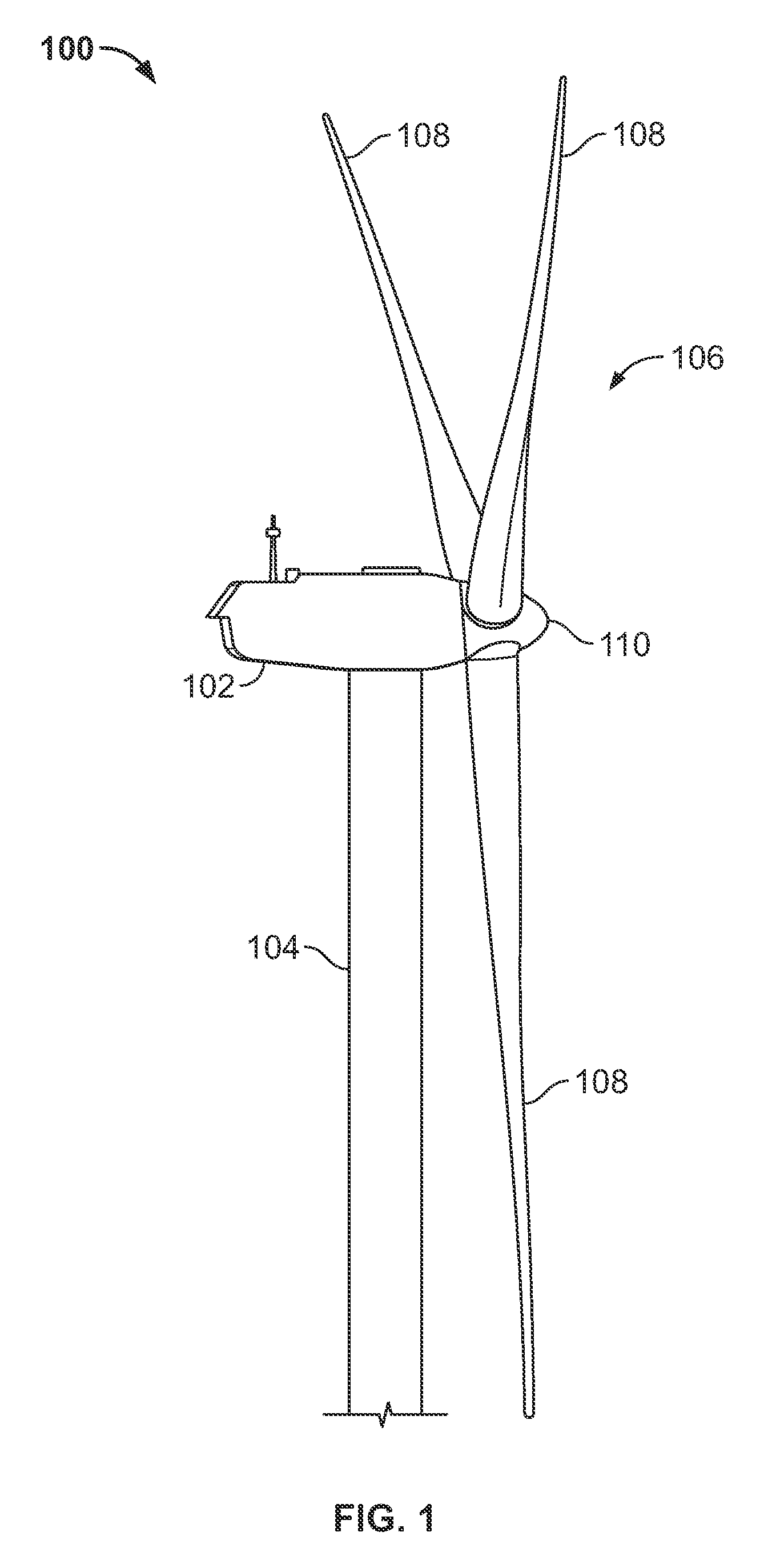
[0019]As shown in FIG. 1, a wind turbine 100 generally comprises a nacelle 102 housing a generator (not shown in FIG. 1). Nacelle 102 is a housing mounted atop a tower 104, only a portion of which is shown in FIG. 1. The height of tower 104 is selected based upon factors and conditions known in the art, and may extend to heights up to 60 meters or more. The wind turbine 100 may be installed on any terrain providing access to areas having desirable wind conditions. The terrain may vary greatly and may include, but is not limited to, mountainous terrain or off-shore locations. Wind turbine 100 also comprises a rotor 106 that includes one or more rotor blades 108 attached to a rotating hub 110. Although wind turbine 100 illustrated in FIG. 1 includes three rotor blades 108, there are no specific limits on the number of rotor blades 108 required by the present invention. As the blades 108 rotate, noise is generated. “Noise level”, “noise” and grammatical variations thereof, as utilized ...


PUM


Abstract

A method for configuring blades of a wind turbine for low noise generation. The method includes providing at least one noise measuring device. The noise measuring device is arranged and disposed in a position to measure noise of the blades during rotation. The wind turbine is configured to include a rotational trigger, the rotational trigger being arranged to provide a signal at a predetermined rotational position of the wind turbine blades. One or more of the blades is configured with an aerodynamic modifying device. Noise level is measured with the noise measuring device during wind turbine operation. The noise produced by each of the blades is determined. The blades are configured in response to the noise determined for each of the blades. A method for measuring the noise level generated by an individual blade and a wind turbine configured for desired noise level are also disclosed.

Description

FIELD OF THE INVENTION[0001]The present invention is directed to methods for installing and / or configuring wind turbines. In particular, the present invention is directed to measuring, analyzing and configuring wind turbines for operation based upon noise level generated by the wind turbine blades.BACKGROUND OF THE INVENTION[0002]Recently, wind turbines have received increased attention as environmentally safe and relatively inexpensive alternative energy sources. With this growing interest, considerable efforts have been made to develop wind turbines that are reliable and efficient.[0003]Generally, a wind turbine includes a rotor having multiple blades. The rotor is mounted to a housing or nacelle, which is positioned on top of a truss or tubular tower. Utility grade wind turbines (i.e., wind turbines designed to provide electrical power to a utility grid) can have large rotors (e.g., 30 or more meters in length). In addition, the wind turbines are typically mounted on towers that ...

Claims


Application Information

Patent Timeline
Patent Type & Authority Applications(United States)
IPC IPC(8): F04D29/66G06F15/00
CPCF03D7/024F03D7/0296F03D11/0091F05B2260/96Y02E10/723F05B2270/333Y02E10/721Y02E10/722F05B2270/326F03D17/00Y02E10/72
Inventor PETERSEN, ANDREASWITTEKIND, LOTHARKRAFT, HEIKO
Owner GENERAL ELECTRIC CO
Why Eureka
Try Eureka