Method to operate an imaging system, and imaging system

a technology of imaging system and imaging system, applied in the field of imaging system operation, can solve the problems of excessive time-consuming method, affecting the development of control sequences, and affecting the quality of imaging methods and image data generated therewith

Active Publication Date: 2010-11-11
SIEMENS HEALTHCARE GMBH
View PDF28 Cites 45 Cited by
  • Summary
  • Abstract
  • Description
  • Claims
  • Application Information

AI Technical Summary

Benefits of technology

[0010]An object of the present invention is to further develop a method to control an imaging system as well as an imaging system such that the quali...

Problems solved by technology

In general, however, no information or at best limited information about the occupation in space (i.e. the position and orientation) and the extent of the different sub-volumes is provided to the technical subsystems.
However, all of these methods deal only with the setting of individual subsystems of the magnetic resonance system.
This method is extraordinarily time-c...

Method used


Image

  • Method to operate an imaging system, and imaging system
  • Method to operate an imaging system, and imaging system
  • Method to operate an imaging system, and imaging system

Examples


Embodiment Construction

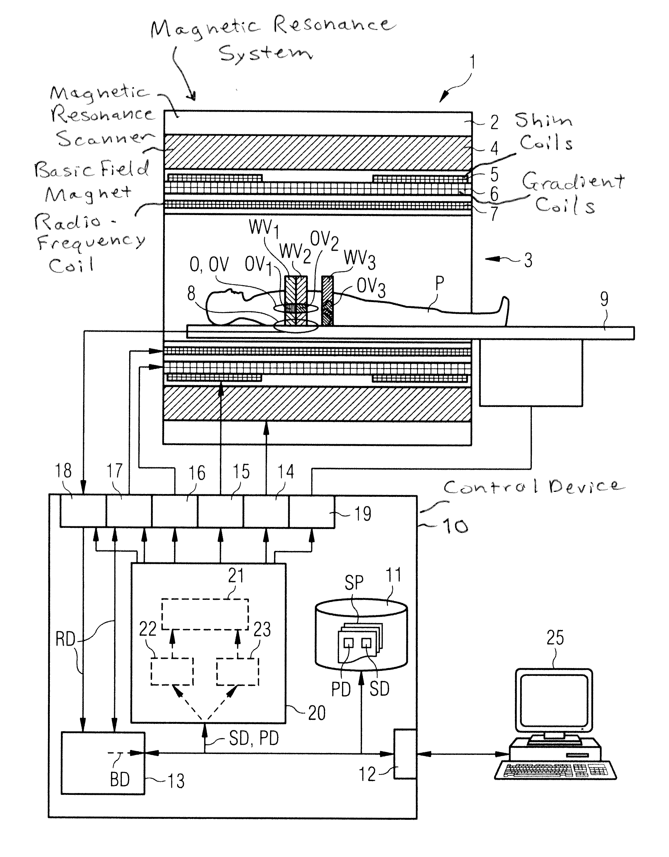
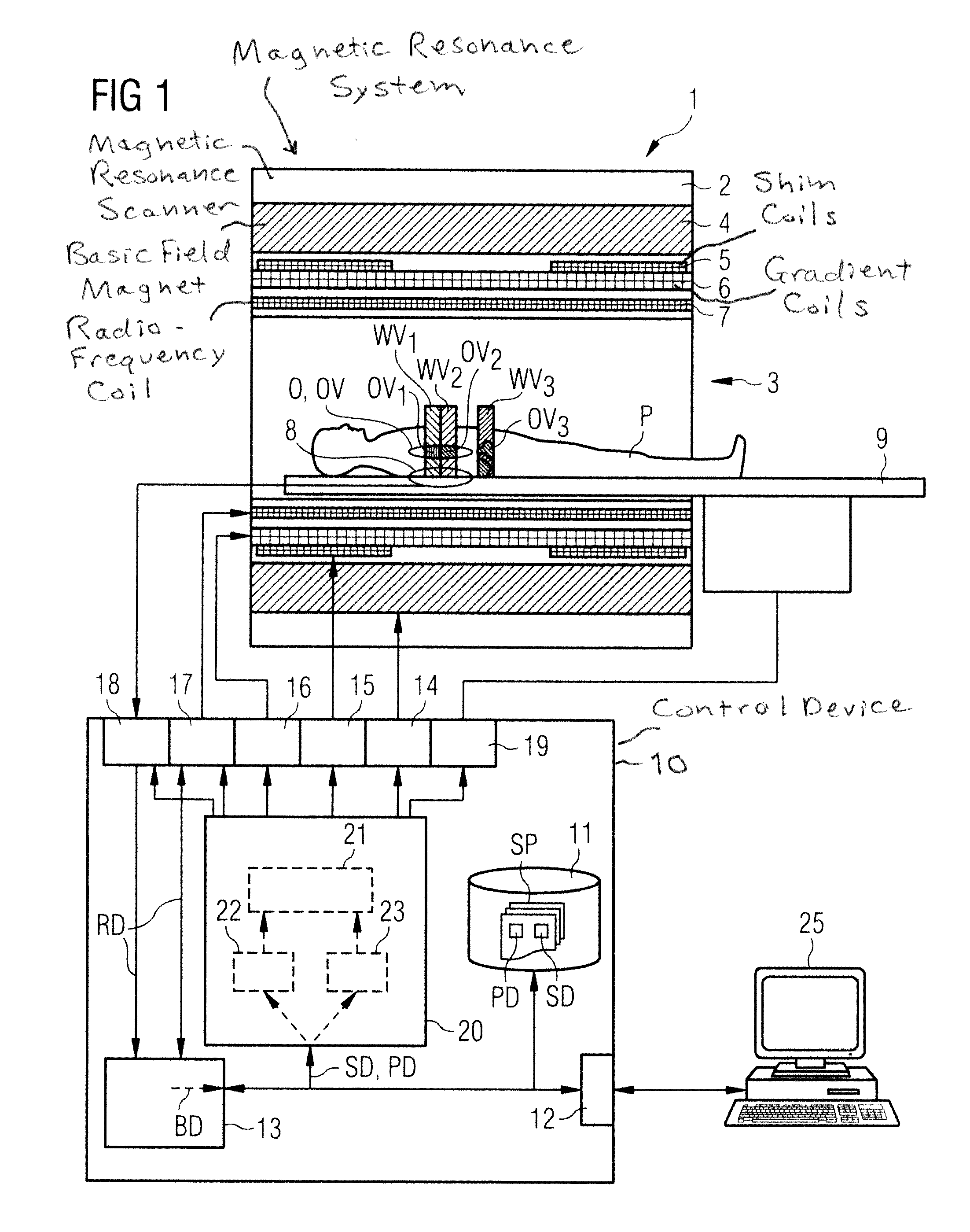
[0033]A magnetic resonance system 1 according to the invention is shown schematically in FIG. 1. It includes the actual magnetic resonance scanner 2 with an examination space 3 or patient tunnel located therein. A bed unit 9 can be driven into this patient tunnel 3 so that, during an examination, a patient P or test subject lying thereupon can be supported at a specific position within the magnetic resonance scanner 2 relative to the magnet system and radio-frequency system arranged in the magnetic resonance scanner 2, or can be moved between different positions during a measurement. At this point it is noted that the precise design of the magnetic resonance scanner 2 is not significant. For example, a cylindrical system with a typical patient tunnel can be used, as well as a C-arm-shaped magnetic resonance apparatus which is open to one side.

[0034]Basic components of the magnetic resonance scanner are a basic field magnet 4, a number of shim coils 5 and magnetic field gradient coil...


PUM


Abstract

In an imaging system having a number of subsystems and a control device that controls the subsystems in a coordinated manner to implement a measurement sequence and an operating method therefor, sequence control data that define different functional sub-sequences of the measurement sequence are transmitted to the control device. Different active volumes are associated with the functional sub-sequences. In addition to the sequence control data, active volume position data are provided to the control device that define bearing and extent of the active volumes associated with the different functional sub-sequences. Control signals to implement the measurement sequence for the different subsystems are generated automatically by the control device based on the sequence control data and the active volume position data so that the individual functional sub-sequences are locally optimized at least with regard to a sub-region of their associated active volume.

Description

BACKGROUND OF THE INVENTION[0001]1. Field of the Invention[0002]The present invention concerns a method to operate an imaging system, in particular a magnetic resonance system, with a number of subsystems and a control device that controls the subsystems in a coordinated manner to implement a measurement sequence. For this sequence control data which define different functional sub-sequences of the measurement sequence are provided to the control device, wherein different active volumes are associated with the functional sub-sequences. Moreover, the invention concerns an imaging system with a number of subsystems and a control device to implement this method.[0003]2. Description of the Prior Art[0004]Tomographical imaging systems (for example magnetic resonance apparatuses or computed tomography systems) are complex installations with multiple technical subsystems. Among these (for example in a magnetic resonance system) are the basic field magnet system in order to expose a body to...

Claims


Application Information

Patent Timeline
IPC IPC(8): G06F17/00
CPCA61B5/055G01R33/546G01R33/54
Inventor FEIWEIER, THORSTENFISCHER, DANIELJESCHKE, HENDRIKSPECKNER, THORSTENSTOECKER, STEPHAN
Owner SIEMENS HEALTHCARE GMBH
Why Eureka
Try Eureka