Instrument for measuring dimensions and height gauge

Active Publication Date: 2010-11-18
TESA SE
View PDF14 Cites 16 Cited by
  • Summary
  • Abstract
  • Description
  • Claims
  • Application Information

AI Technical Summary

Benefits of technology

[0019]Furthermore, the inventive measuring instrument preferably includes one or several additional elastic connections or a device for limiting the driving force by means of a friction element in order to protect the force sensor. One of the first additional elastic elements that is situated at the level of the driving system control enables a limitation of the force exerted by the operator or the motor when the probe comes into contact with the part to be measured. Other elastic elements can be added serially to the force sensor to increase the elastic displacement limits of the measuring system and thus protect the sensor. As the elastic deformation does not influence the measurement of the position, adding these protection devices is not limited. It will also be possible to add stops and/or elements parallel to the force sensor in order not to exceed the admissible deformation limit of the sensor and thus shunt mechanical overloads.
[0020]The direct reading of the contact force enables this fundamental measuring parameter to be better controlled. Indeed, the contact force can have a dimensional influence on certain materials. Therefore, a finer measurement of the exerted contact force makes it possible to interpolate from several measurements of different contact forces the elasticity of the measured material and thus also to extrapolate from the actual dimension of the measured part that would be achieved with a zero contact force corresponding to a zero elastic deformation. Furthermore, with a zero contact force, the dimension of the part to be measured is no longer influenced by parasite contact forces in the case where surfaces are measured that

Problems solved by technology

This limits the field of application of these devices.
These simpler devices however do not permit to measure a force overshoot during measurement.
Furthermore, this device does not allow the measuring conditions and notably the pressing force of the probe during measurement to be varied or corrected.
These low-cost sensors however have some flaws, as they do not provide information referenced accurately and do not afford perfect correspondence with the contact force, their calibration is likely

Method used


Image

  • Instrument for measuring dimensions and height gauge
  • Instrument for measuring dimensions and height gauge
  • Instrument for measuring dimensions and height gauge

Examples


Embodiment Construction

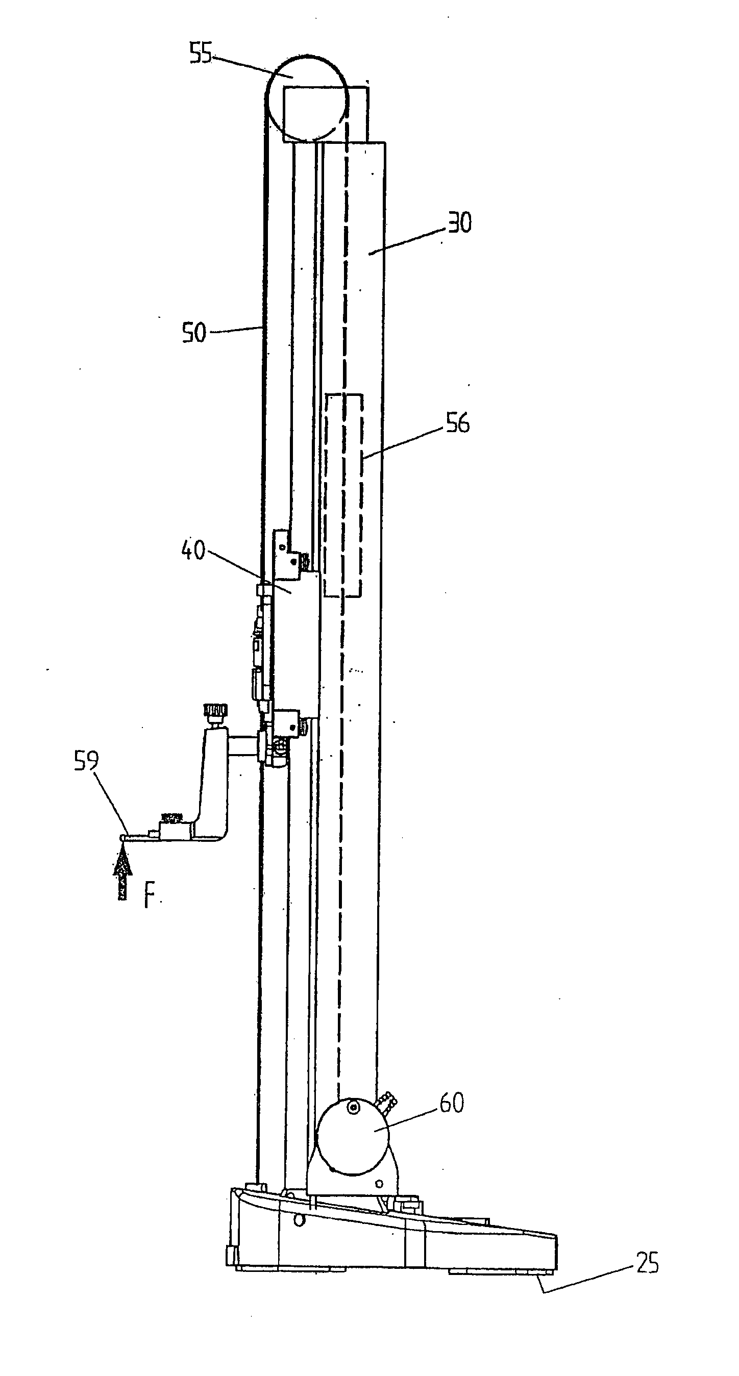
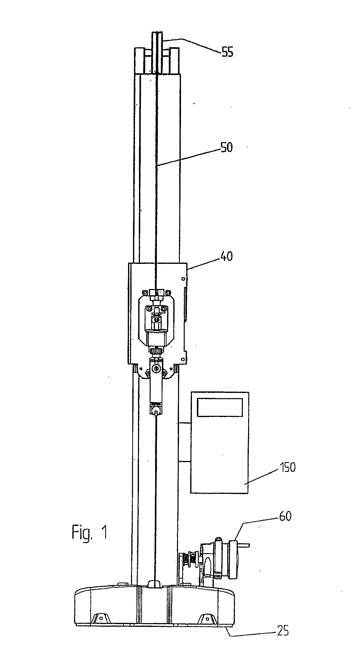
[0030]The height gauge of FIG. 1 comprises a solebase 25 designed to rest against a reference plane and a vertical frame 30 comprising a position reference defining a vertical measuring axis. The carriage 40 slides along the frame 30 and its position is read by a position encoder, not visible in the figure. The position encoder is preferably an optical encoder capable of reading the carriage's position with a precision on the order of, or greater than, the micrometer. Other position measuring systems are however also possible.

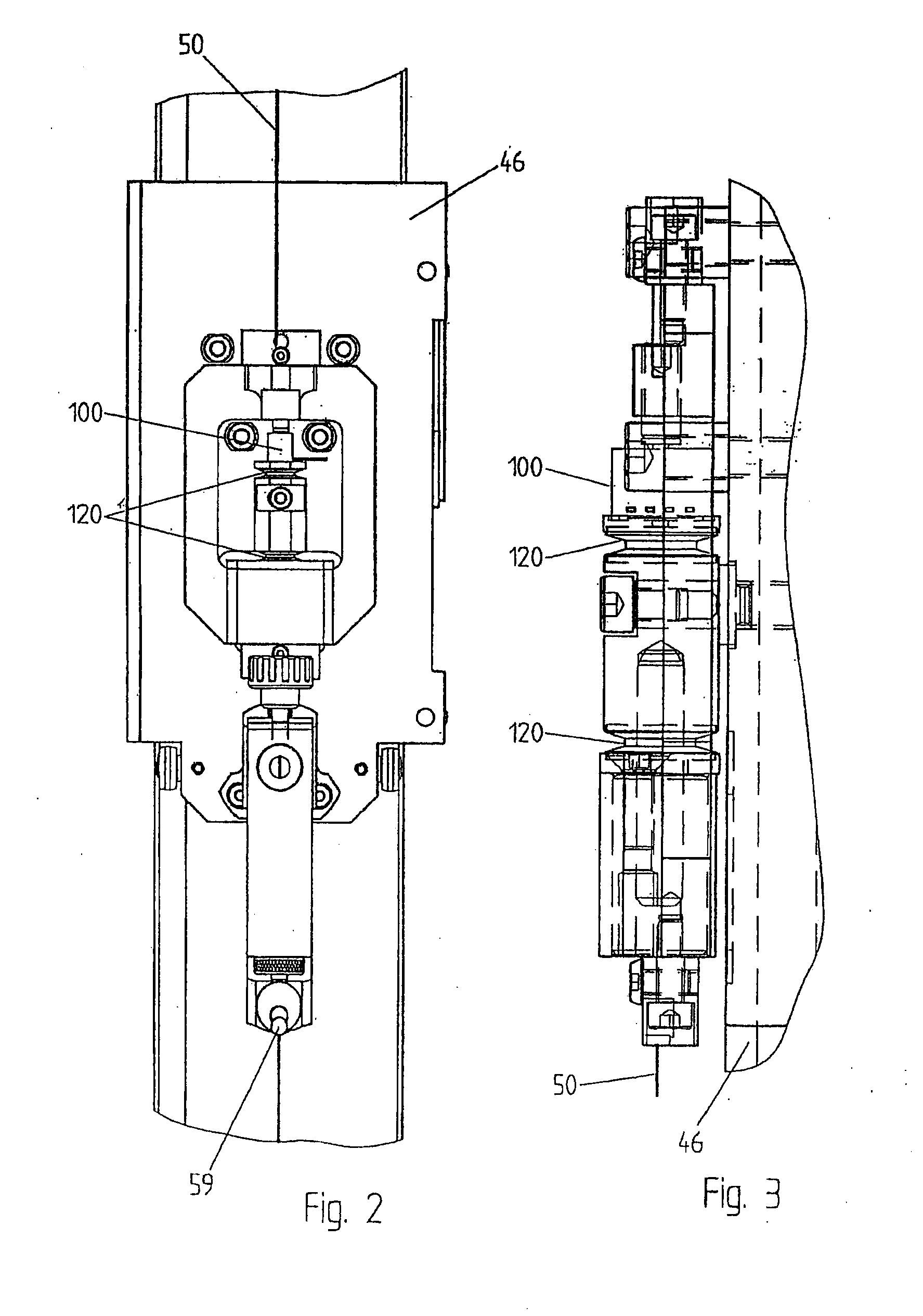
[0031]The movement of the carriage 40 is ensured through the force sensor 100, through the cable 50 forming a closed loop around the upper pulley 55 and a lower pulley, not visible. The lower pulley is driven by the handle 60 that can be actuated by the operator and that allows the carriage 40 to move. A counterweight 56 (visible in FIG. 4) counterbalances the weight of the carriage. The probe 59, preferably interchangeable, is brought into contact with the sur...


PUM


Abstract

Instrument for measuring dimensions, including: a mobile carriage capable of moving parallel to a guide, the guide defining a measuring axis; a driving device connected to the carriage by a transmission, so as to determine the linear displacement of the mobile carriage; a feeler attached to the mobile carriage and designed to come into contact with a part to be measured; a position transducer, arranged so as to supply a measurement of the feeler's position relative to the measuring axis; a piezoresistive force sensor for converting directly a contact force between the feeler and the part to be measured into an electric signal.

Description

REFERENCE DATA[0001]This application claims priority from European Patent Application EP09160174 filed on May 13, 2009.TECHNICAL FIELD[0002]The present invention concerns an instrument for measuring dimensions along a linear axis, in particular, but not exclusively, an instrument for measuring linear dimensions along a vertical and a horizontal measuring axis.STATE OF THE ART[0003]Measuring instruments such as height gauges and machines for measuring coordinates are used for measuring and controlling the dimensions of high precision mechanical parts. They supply measurements with an accuracy and reproducibility on the order of the micrometer.[0004]These instruments allow relative measurements as well as absolute measurements to be performed. They are generally associated to a horizontal plane table or a measuring bench on which the part to be measured or controlled is placed in a chosen position so that this common element constitutes a reference plane between the device and the par...

Claims


Application Information

Patent Timeline
IPC IPC(8): G01B5/02
CPCG01B5/008
Inventor BISELX, FREDERIC
Owner TESA SE
Why Eureka
Try Eureka