Choke Assembly

a choke and assembly technology, applied in the direction of process and machine control, wellbore/well accessories, instruments, etc., can solve the problems of reducing the efficacy of the choke in controlling fluid flow and pressure, reducing the effectiveness of the choke, and reducing the pressure drop of the forced fluid, so as to reduce the pressure and increase the force of the forced fluid. , the effect of discharging the energy of the fluid flow

Active Publication Date: 2010-11-18
CAMERSON INT CORP
View PDF13 Cites 26 Cited by
  • Summary
  • Abstract
  • Description
  • Claims
  • Application Information

AI Technical Summary

Benefits of technology

[0059]In order to prevent the cage from unnecessarily restricting the flow of fluid through the choke when the choke assembly is fully open, it is preferred that the total area of the apertures available for the flow of fluid is greater than the cross-sectional area of the fluid inlet of the choke assembly.
[0060]In use, the choke of this aspect of the invention operates under a combined regime of physical choking or throttling of the fluid flowing through the apertures in the cage and hydraulic choking or throttling. Conventional choke assemblies reduce the pressure and control the flow of f

Problems solved by technology

A particular problem exists with the aforementioned conventional design of plug and cage choke assembly, in that the flow of fluids through the apertures past the end of the plug erodes the surfaces of both the plug and the cage.
Erosion of the sealing end portion of the plug reduces the effectiveness of the plug in sealing the apertures in the cage, in turn reducing the efficacy of the choke in controlling fluid flow and pressure.
In addition, the erosion of the sealing end portion of the plug reduces the efficiency of the seal between the end portion and the seat of the plug when in the closed position.
Fluid streams containing significant amounts of entrained solids will give rise to a very high rate of erosion of the both the plug and the cage, very rapidly reducing the efficiency of operation of the choke assembly.
However, the servicing of choke assemblies is a particular problem in the case of processing installations in remote or difficult-to-reach locations.
This problem is particularly acute in the case of choke assemblies installed in subsea wellhead installations.
The replacement of a choke assembly in a wellhead installation may be particularly difficult if the choke assembly is required in order to maintain the integrity of the well.
This problem is exacerbated in the case of wellhead installations insta

Method used


Image

  • Choke Assembly
  • Choke Assembly
  • Choke Assembly

Examples


Embodiment Construction

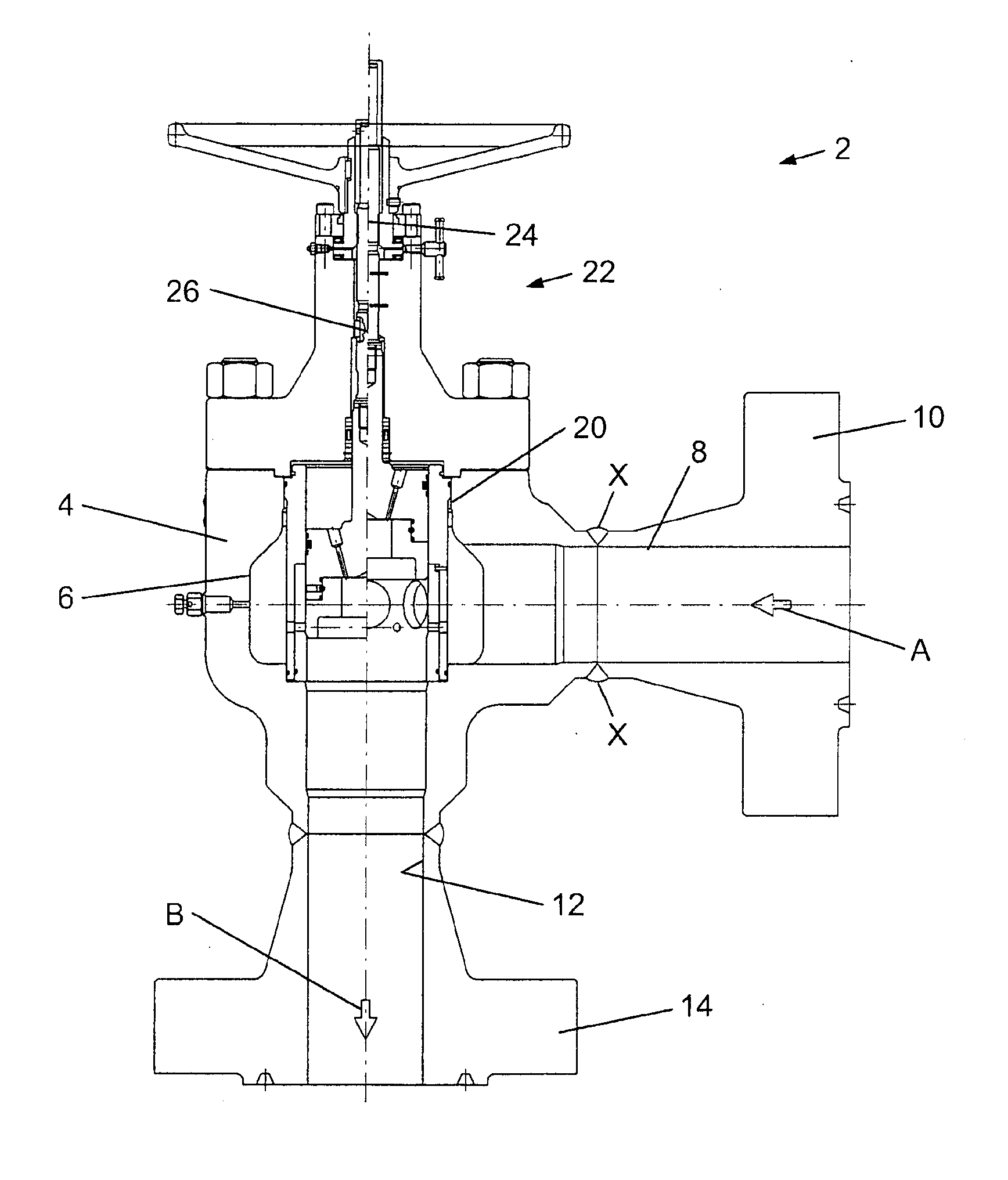
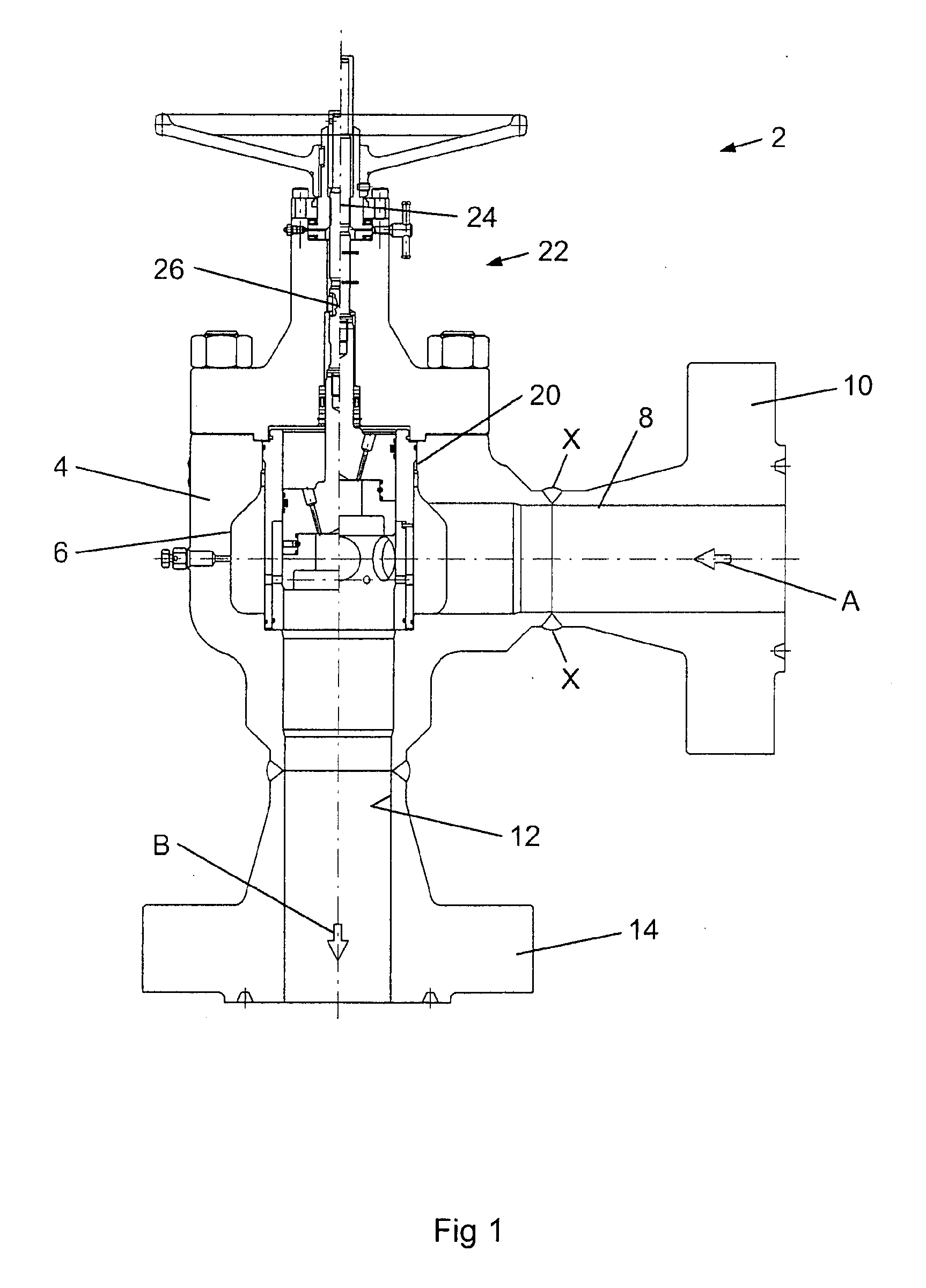
[0087]Referring to FIG. 1, there is shown a choke assembly, generally indicated as 2. The choke assembly 2 is largely of conventional design and comprising a choke body 4 having a generally cylindrical choke cavity 6 formed therein. A fluid inlet 8 is provided in the side of the choke body 4, terminating in a flange coupling 10 of conventional design and provides a passage for fluid to enter the choke cavity 6 from a lateral direction, as indicated by arrow A in FIG. 1. A fluid outlet 12 is provided in the choke body 4, extending longitudinally from the choke cavity 6 and terminating in a flange coupling 14, again of conventional design. The fluid outlet 12 provides a passage for fluid leaving the choke cavity 6, as indicated by the arrow B in FIG. 1. The choke assembly further comprises a choke element, generally indicated as 20, of the plug-and-cage type, disposed coaxially within the choke cavity 6, as will be described in more detail hereafter. An actuator assembly 22 is mounted...


PUM


Abstract

A choke assembly. In some embodiments, the choke assembly includes a choke element having a fluid flow passage therethrough. The choke element includes a cage having a plurality of apertures therethrough for the passage of fluid and a plug moveable with respect to the cage. The plug has an end surface that defines a boundary of the fluid flow passage through the choke and is moveable to open or close each of the apertures through the cage, whereby the flow of fluid through the cage is controlled. The apertures in the cage are disposed in a first portion and a second portion separated by a land. Each of the first and second portions has a least one aperture therein. The plug may be positioned with its end surface disposed to intersect the land, such that each aperture is fully open or fully closed to the flow of fluid.

Description

CROSS-REFERENCE TO RELATED APPLICATIONS[0001]Not applicable.STATEMENT REGARDING FEDERALLY SPONSORED RESEARCH OR DEVELOPMENT[0002]Not applicable.BACKGROUND[0003]The present invention relates to a choke assembly, in particular to a choke assembly having a plug and cage type arrangement, and to the use of the choke assembly in the processing of fluid streams. The present invention further relates to a wellhead assembly comprising the choke assembly, in particular a subsea wellhead assembly. The present invention further provides a method of operating a choke assembly and for controlling the pressure of a fluid stream.[0004]Choke assemblies are well known and widely used in an extensive range of fluid processing applications. One particular application of chokes assemblies is in the processing of fluid streams produced from subterranean oil and gas wells, in particular in installations associated with the wellhead. The principle function of a choke assembly is to control the pressure an...

Claims


Application Information

Patent Timeline
IPC IPC(8): G05D7/01
CPCE21B34/02E21B43/12F16K3/246F16K47/08F16K25/04F16K47/04F16K3/32
Inventor HOPPER, HANS PAULMEEK, DEREK
Owner CAMERSON INT CORP
Why Eureka
Try Eureka