Aircraft High Lift System and Method for Determining an Operating Condition of an Aircraft High Lift System

a technology of high-lift systems and aircraft, which is applied in the field can solve problems such as inability to detect jamming cases in actuating gear and/or transmission, inability to actuate and move wing flaps such as landing flaps and leading-edge flaps of aircraft, and inadmissible operating conditions or error conditions of aircraft high-lift systems, so as to facilitate localization of possible errors and facilitate communication. the effect of simple construction of the aircraft high

Active Publication Date: 2010-11-18
LIEBHERR AEROSPACE LINDENBERG
View PDF5 Cites 36 Cited by
  • Summary
  • Abstract
  • Description
  • Claims
  • Application Information

AI Technical Summary

Benefits of technology

[0018]This provides the advantage that a simple construction of the aircraft high lift system becomes possible. At the same time, a localization of a possible error is facilitated, since by assigning the signal to the detection means, whose arrangement in turn is known, the error location within the system is easily communicated. Furthermore, it is particularly advantageous that the error and also the error location can directly be communicated to the pilot.
[0019]Furthermore, it can be provided that by means of the detection means the torque applied and / or the time course of the torque can be detected and / or that the detection means is a torque sensor. This provides the advantage that the easily evaluatable characteristic of the torque or torque profile can be utilized for determining the operating condition and correspondingly also for faulty operating conditions. In the aircraft high lift system, reference values and / or curves or patterns for example can be stored in suitable means, which can be matched with current values. By such indirect evaluation, detailed conclusions as to the operating condition can already be made possible with a small number of detection means. Moreover, by means of the reference values and / or curves or patterns a detailed statement as to the kind of error and the error location in one and / or both of the load stations of a flap can already be made possible with only one single detection means.
[0020]It is furthermore conceivable that no mechanical torque limiter is present, in particular that no mechanical torque limiter is present on the output side of a transfer gear in the transmission branching off actuating energy provided by a central drive unit and / or that no mechanical torque limiter is present in a load station. This provides the advantage that the aircraft high lift system can be constructed simpler and lighter in weight. Due to the omission of the highly complex and heavy components, the prime costs, but also the maintenance costs are decreased, since the maintenance requirements can be reduced in addition.

Problems solved by technology

Aircraft high lift systems which actuate and move wing flaps such as landing flaps and leading-edge flaps of the aircraft can get into inadmissible operating conditions or error conditions.
Jamming cases in the actuating gear and / or in the transmission are, however, not detectable with this system.
Depending on the design of the structural components and the drive and guiding elements, the error can also remain unnoticed up to the next maintenance interval.
Furthermore, in the known aircraft high lift systems with mechanical torque limiter a localization of the error location generally can only be effected by visual inspection of the mechanical indications on the load limiters.
Furthermore, the evaluation unit can communicate the current operating conditions to the pilot and also possibly issue warnings in the case of faulty operating conditions via an output unit such as a monitor or a control instrument in the cockpit.

Method used


Image

  • Aircraft High Lift System and Method for Determining an Operating Condition of an Aircraft High Lift System
  • Aircraft High Lift System and Method for Determining an Operating Condition of an Aircraft High Lift System
  • Aircraft High Lift System and Method for Determining an Operating Condition of an Aircraft High Lift System

Examples


Embodiment Construction

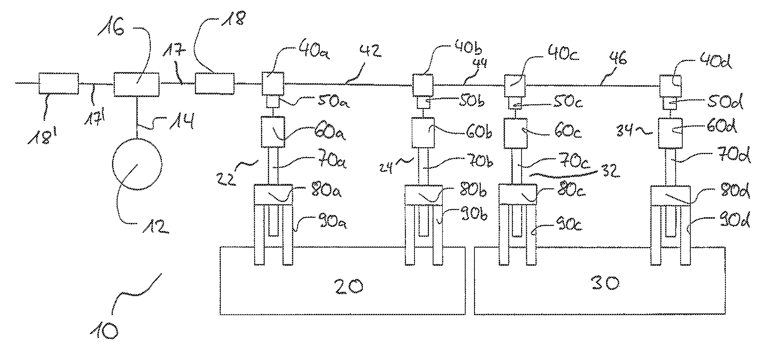
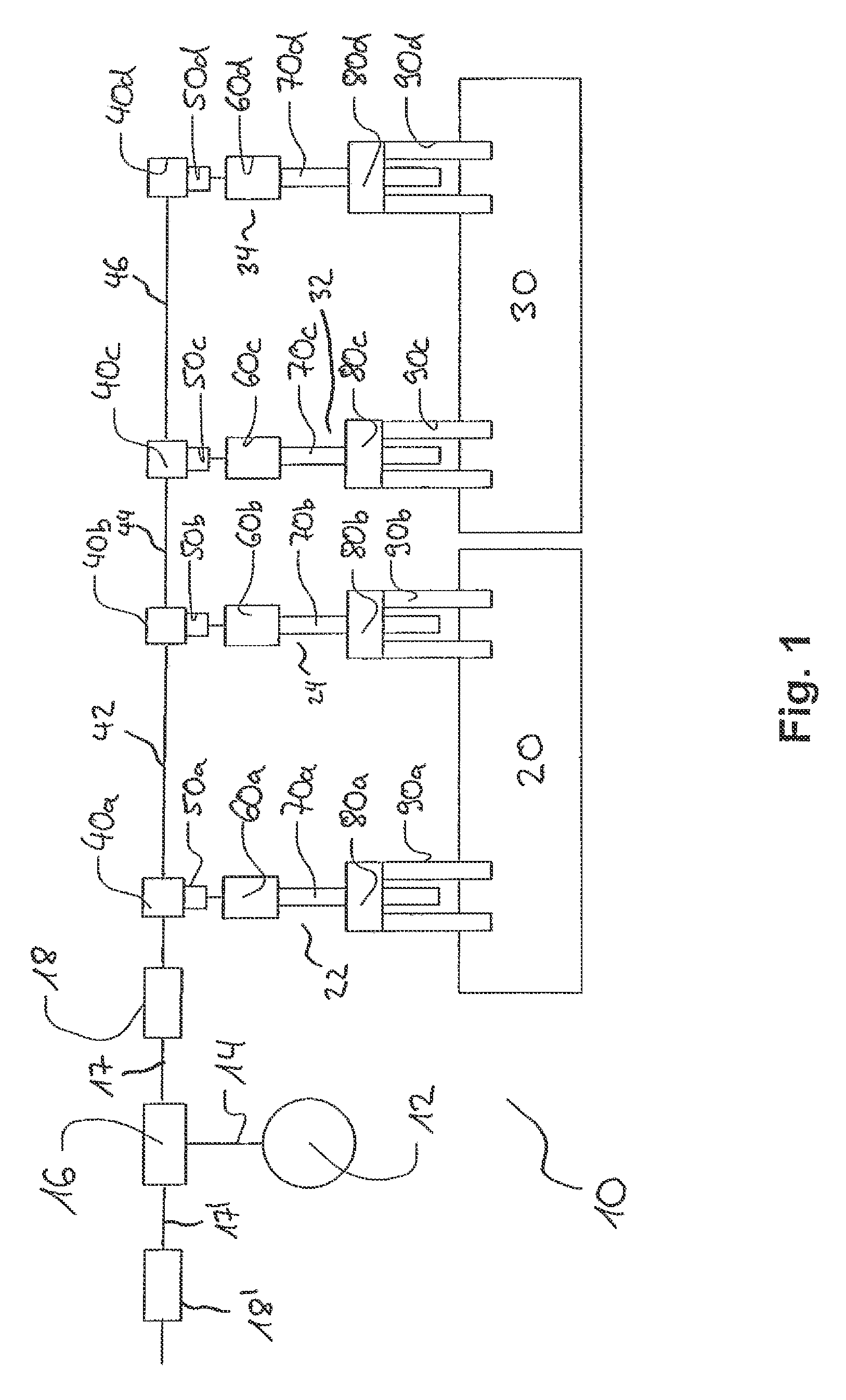
[0049]FIG. 1 shows a known aircraft high lift system 10 in a schematic representation. The aircraft high lift system 10 includes a central drive unit 12, by means of which electric or hydraulic energy of the aircraft supply is converted into mechanical actuating energy. By means of non-illustrated braking means, the aircraft high lift system can be maintained in position.

[0050]Via a central shaft 14, the central drive unit 12 transmits the actuating energy from the central drive unit 12 to a transfer gear 16, which distributes the actuating energy to the transmission 17 of the right wing and to the transmission 17′ of the left wing. In the embodiment shown in FIG. 1, the construction of the aircraft high lift system substantially is only shown for the right wing.

[0051]On the output side of the transfer gear 16, a torque limiter 18, 18′ is each provided, which on overload blocks the drive and dissipates the actuating torque into the non-illustrated supporting structure, in particular...


PUM


Abstract

The present disclosure relates to an aircraft high lift system with at least one load station for actuating a flap of a wing, preferably a landing flap and/or a leading-edge flap, at least one transmission with transmission portions located between branch transmissions, wherein by means of the branch transmissions actuating energy can be branched off from the transmission to the load station, and to a method for determining an operating condition of an aircraft high lift system.

Description

CROSS REFERENCE TO RELATED APPLICATION[0001]This application claims priority to German Patent Application No. 10 2009 020 840.2, filed May 12, 2009, which is hereby incorporated by reference in its entirety for all purposes.TECHNICAL FIELD[0002]The present disclosure relates to an aircraft high lift system with at least one load station for actuating a flap of a wing, preferably a landing flap and / or a leading-edge flap, and at least one transmission with transmission portions located between branch transmissions, wherein by means of the branch transmissions actuating energy can be branched off from the transmission to the load station, and to a method for determining an operating condition of an aircraft high lift system.BACKGROUND AND SUMMARY[0003]Aircraft high lift systems which actuate and move wing flaps such as landing flaps and leading-edge flaps of the aircraft can get into inadmissible operating conditions or error conditions. For safety reasons, it is necessary to immediat...

Claims


Application Information

Patent Timeline
Patent Type & Authority Applications(United States)
IPC IPC(8): G05D1/00
CPCB64D2045/001B64D45/0005
Inventor SCHIEVELBUSCH, BERNDHAUBER, BERNHARD
Owner LIEBHERR AEROSPACE LINDENBERG
Why Eureka
Try Eureka