Damascene coil processes and structures

a technology of damascene coils and processes, applied in the field of hard drives, can solve the problems of inferior process control and overlay control, process is less than robust, and the i-line lithography tool suffers from a number of drawbacks, so as to eliminate the problem of insulation coverage

Inactive Publication Date: 2010-11-18
WESTERN DIGITAL TECH INC
View PDF24 Cites 156 Cited by
  • Summary
  • Abstract
  • Description
  • Claims
  • Application Information

AI Technical Summary

Benefits of technology

[0005]Various embodiments of the present invention solve the foregoing problems by providing improved damascene coils and methods for manufacturing the same. A patterned photoresist layer is used to transfer a coil pattern into one or more hard mask layers, which are then subjected to an etching process to transfer the coil pattern into a substrate, such as alumina or a rigid polymer. Because only a thin layer of photoresist is needed to transfer the coil pattern to the hard mask, higher resolution photolithography equipment (e.g., deep ultraviolet) can be used. Moreover, the substrate into which the coil is plated may be an insulator, obviating the need for a secondary photoresist patterning step and eliminating the insulation coverage problems of other approaches.

Problems solved by technology

I-line lithography tools, however, suffer from a number of drawbacks, including inferior process control and overlay control.
Moreover, this process is less than robust, experiencing around 1% yield loss.
Finally, I-line lithography tools have fairly low resolution (compared to other lithography tools), reducing their ability to provide magnetic recording devices with increasingly smaller coil linewidth.
The poor overlay capability of the I-line lithography tool often causes insulation coverage problems, which may negatively impact the performance of the coil.
The photoresist cap is then cured using a high-temperature bake process that may last for several hours, a process which creates manufacturing challenges (e.g., as the photoresist tends to flow when heated) and may cause product reliability issues.

Method used


Image

  • Damascene coil processes and structures
  • Damascene coil processes and structures
  • Damascene coil processes and structures

Examples


Embodiment Construction

[0016]In the following detailed description, numerous specific details are set forth to provide a full understanding of the present invention. It will be apparent, however, to one ordinarily skilled in the art that the present invention may be practiced without some of these specific details. In other instances, well-known structures and techniques have not been shown in detail to avoid unnecessarily obscuring the present invention.

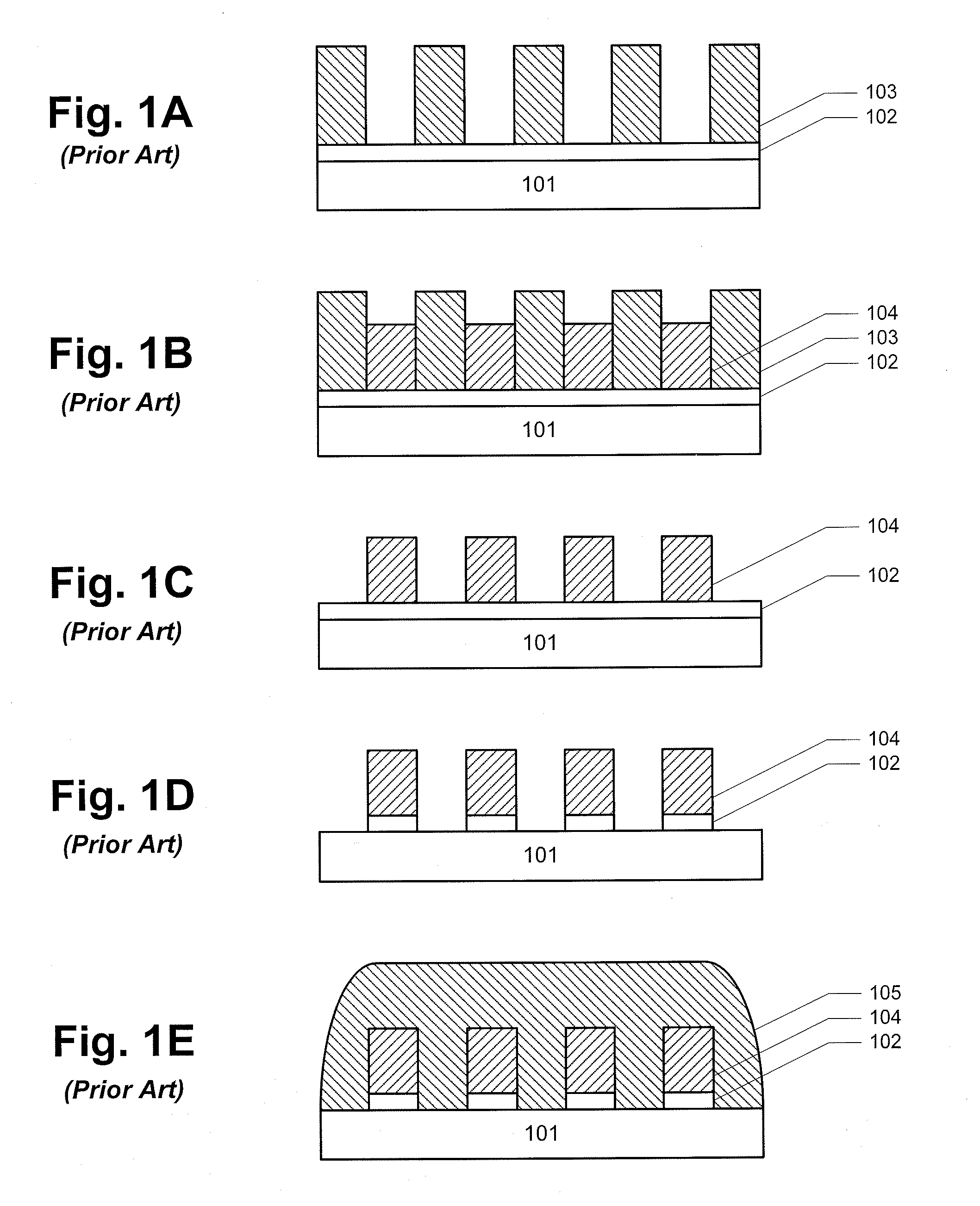
[0017]One conventional approach for forming a coil for a magnetic recording head is illustrated in FIGS. 1A to 1E. As can be seen with reference to FIG. 1A, the process begins by patterning a thick layer of photoresist 103 over a seed layer 102 and a substrate 101. The photoresist pattern defines the turns of the coil, and must be at least as high as the height of the turns thereof (e.g., at least 2 μm for many coils, and frequently 3-4 μm). As shown in FIG. 1B, the conductive material of the coil 104 (e.g., Cu) is electroplated into the patterned opening...


PUM

PropertyMeasurementUnit
thicknessaaaaaaaaaa
thicknessaaaaaaaaaa
wavelengthaaaaaaaaaa

Abstract

A magnetic recording head is provided. The magnetic recording head comprises a write pole and a write coil structure configured to generate a magnetic field in the write pole. The write coil structure comprises a substrate layer and a coil material disposed within the substrate layer. The write coil structure is substantially free of photoresist. A method for forming a write coil structure is also provided. The method comprises the steps of providing a substrate layer, forming a photoresist pattern mask over the substrate layer, opening a damascene trench in the substrate layer by reactive ion etching, and disposing a coil material into the damascene trench in the substrate layer.

Description

FIELD OF THE INVENTION[0001]The present invention generally relates to hard drives and, in particular, relates to damascene coil processes and structures.BACKGROUND[0002]Hard disk drives include one or more rigid disks, which are coated with a magnetic recording medium in which data can be stored. Hard disk drives further include read and write heads for interacting with the data in the magnetic recording medium. The write head includes an inductive coil for generating a magnetic field in a write pole, whereby the magnetic moments of domains in the magnetic recording medium are aligned to represent bits of data.[0003]One approach to forming the coil involves patterning a thick layer of photoresist using an I-line stepper, to form a coil shaped cavity in the photoresist into which the coil material will be plated. An I-line stepper is used to provide sufficient depth-of-focus to pattern the photoresist, which may have a thickness of several microns (e.g., as determined by the desired...

Claims


Application Information

Patent Timeline
Patent Type & Authority Applications(United States)
IPC IPC(8): G11B5/17B05D3/00B44C1/22C25D5/34
CPCG11B5/17C25D7/123G11B5/3123
Inventor ZHANG, JINQIUYUAN, HONGPINGSUN, HAIZHAO, MING
Owner WESTERN DIGITAL TECH INC
Why Eureka
Try Eureka