Nanocalorimeter based on thermal probes

a thermal probe and nanocalorimeter technology, applied in the direction of instruments, heat measurement, material heat development, etc., can solve the problems of ineffective monitoring of a large number of reactions, system failure to measure very small samples,

Active Publication Date: 2010-11-18
XEROX CORP
View PDF34 Cites 15 Cited by
  • Summary
  • Abstract
  • Description
  • Claims
  • Application Information

AI Technical Summary

Problems solved by technology

As such, these systems cannot be used to measure very small samples, as might be desired for precious or highly reactive materials.
Furthermore, standard calorimeters cannot be

Method used


Image

  • Nanocalorimeter based on thermal probes
  • Nanocalorimeter based on thermal probes
  • Nanocalorimeter based on thermal probes

Examples


Embodiment Construction

[0022]Calorimetry is a powerful method for characterizing biochemical interactions. It does not require labeling or immobilization of reagents, so concerns about the effects of such modifications on the behavior of the reagents are eliminated. At the same time, assay development time and cost can be minimized because neither labeling nor immobilization protocols need to be established. For binding reactions, calorimetry can be used to provide a complete thermodynamic characterization. However, as mentioned in the Background, the use of conventional calorimetry is limited by large sample requirements and low throughput. Enthalpy array technology to enable calorimetry on a scale 200-times smaller than available with commercially available state of the art systems, which substantially reduces reagent costs has been developed. See for example, U.S. Pat. Nos. 7,147,763 and 7,141,210. By enabling parallel measurements, these approaches also reduce the measurement time by 100-fold. Both of...


PUM


Abstract

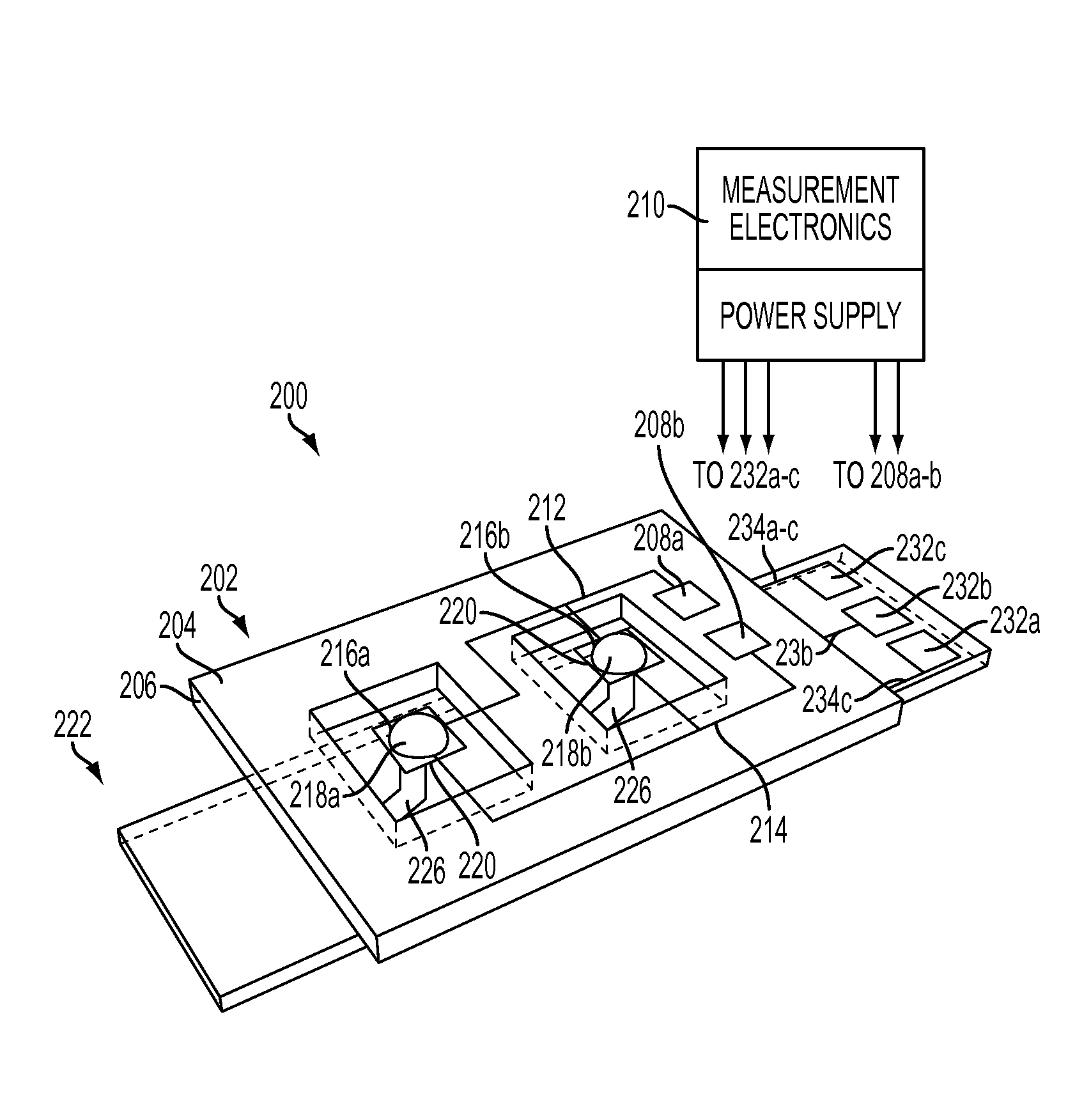
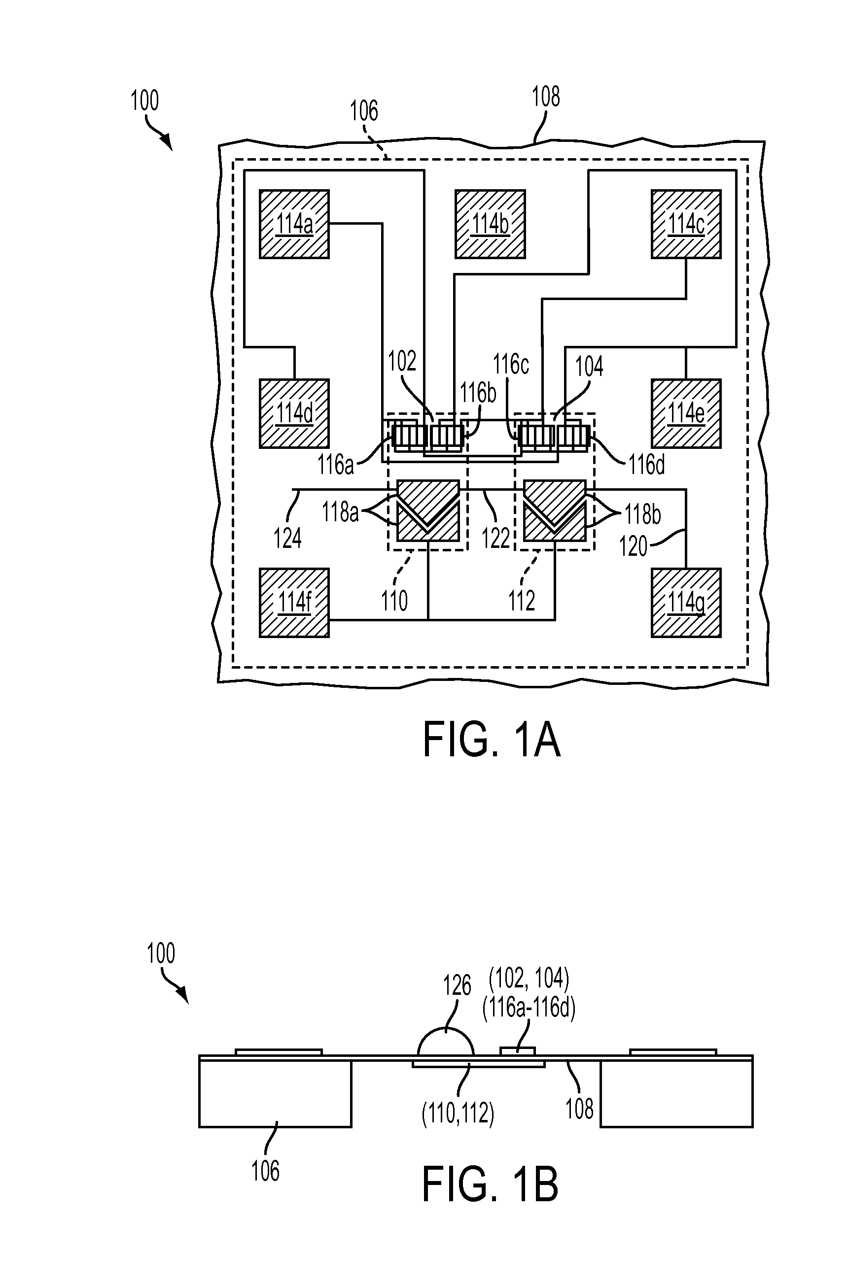
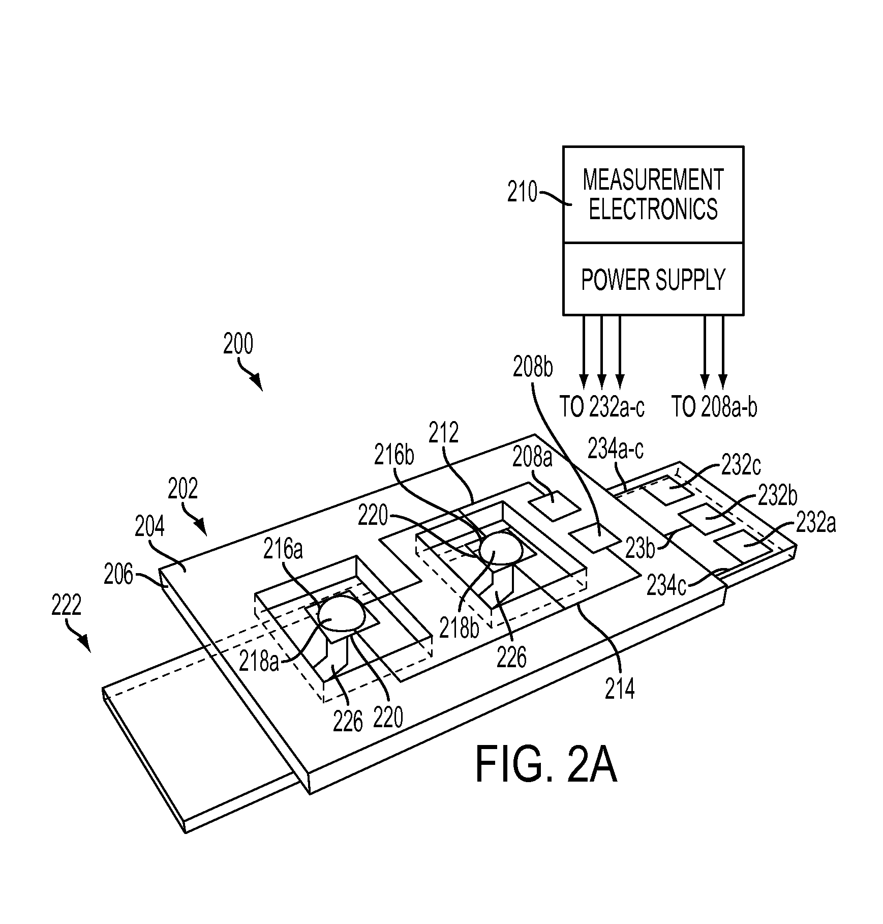
A nanocalorimeter includes a merging layer having, a drop placement area for holding drops to be merged and a thermal equilibration area. A measurement layer includes a substrate, and a temperature probe on the substrate, wherein the temperature probe extends out of the surface of the substrate to come into operative contact with the thermal equilibration area when the measurement layer is placed in operative association with the merging layer. The nanocalorimeter is configured to have the merging layer and the measurement layer non-integrated, making the measurement layer reusable.

Description

INCORPORATION BY REFERENCE[0001]U.S. Pat. No. 7,521,253, titled, Method for multiple target assay for drug discovery; U.S. Pat. No. 7,473,031, titled, Resistive thermal sensing; U.S. Pat. No. 7,473,030, titled, Thermal sensing; U.S. Pat. No. 7,419,835, titled, Screening for ligand binding at specific target sites; U.S. Pat. No. 7,416,897, titled, Method for high-throughput screening assay sample preparation and analysis; U.S. Pat. No. 7,413,706, titled, Replaceable parylene membranes for nanocalorimeter; U.S. Pat. No. 7,147,763, titled, Apparatus and method for using electrostatic force to cause fluid movement; U.S. Pat. No. 7,141,210, titled, Apparatus and method for a nanocalorimeter for detecting chemical reactions; U.S. Pat. No. 7,230,440, titled, Curved spring structure with elongated section located under cantilevered section; U.S. Pat. No. 7,082,684, titled, Intermetallic spring structure; U.S. Pat. No. 6,973,722, titled, Release height adjustment of stress metal device by an...

Claims


Application Information

Patent Timeline
IPC IPC(8): G01K17/00
CPCG01K17/006B82Y35/00G01K2211/00
Inventor DE BRUYKER, DIRKTORRES, FRANCISCO E.WOLKIN, MICHAL V.ANDERSON, GREGORY B.CHOW, EUGENE M.
Owner XEROX CORP
Why Eureka
Try Eureka