

Sealing device
- Summary
- Abstract
- Description
- Claims
- Application Information
AI Technical Summary
Benefits of technology
Problems solved by technology
Method used
Image

Examples
example 1
[0047]Details of an additive used in Example 1 are those shown in the following Table 1.
TABLE 1MolecularMelting pointAdditive No.TypeMaterial nameweight(° C.)1Metal soapLi metal soapLithium stearate2892162Organic acidUnsaturated fatty acid monoamideOleic acid amide (purified oleic acid amide)281753amideSubstituted amideN-Stearyl erucic acid amide589694Saturated fatty acid bisamideEthylenebisstearic acid amide5921455UreaSubstituted ureaXylylene bisstearyl urea7261666Substituted ureaDiphenylmethane bisstearyl urea802206Number of carboxylNumberNumber of carboxylbond, amide bondof longbond, amide bondor urea bond in onechain in oneor urea bond perNumber of longAdditive No.moleculemoleculegramchain per gramTrade name1112.1E+212.1E+21Trade name: S-7000, manufactured by SakaiChemical Industry Co., Ltd.2112.1E+212.1E+21Trade name: DIAMID O-220, manufacturedby Nippon Kasei Chemical Co., Ltd.3121.0E+212.0E+21Trade name: NIKKAMIDE SE, manufacturedby Nippon Kasei Chemical Co., Ltd.4232.0E+213.1...
example 2
[0061]NBR [containing carbon black and graphite] was used as a rubber component; lithium stearate [product number: S-7000, manufactured by Sakai Chemical Industry Co., Ltd.] was used as a metal soap; purified oleic acid amide [trade name: DIAMID 0-200, manufactured by Nippon Kasei Chemical Co., Ltd.] was used as an organic acid amide; and dimethylsilicone-supported silica (silicone compound) [trade name: TORAYFIL F-202, manufactured by Dow Corning Toray Co., Ltd. (oil content: 50 to 65% by mass, oil kinematic viscosity: about 60,000 cs, particle size: 10 to 100 μm)] was used as an oil-containing particle.
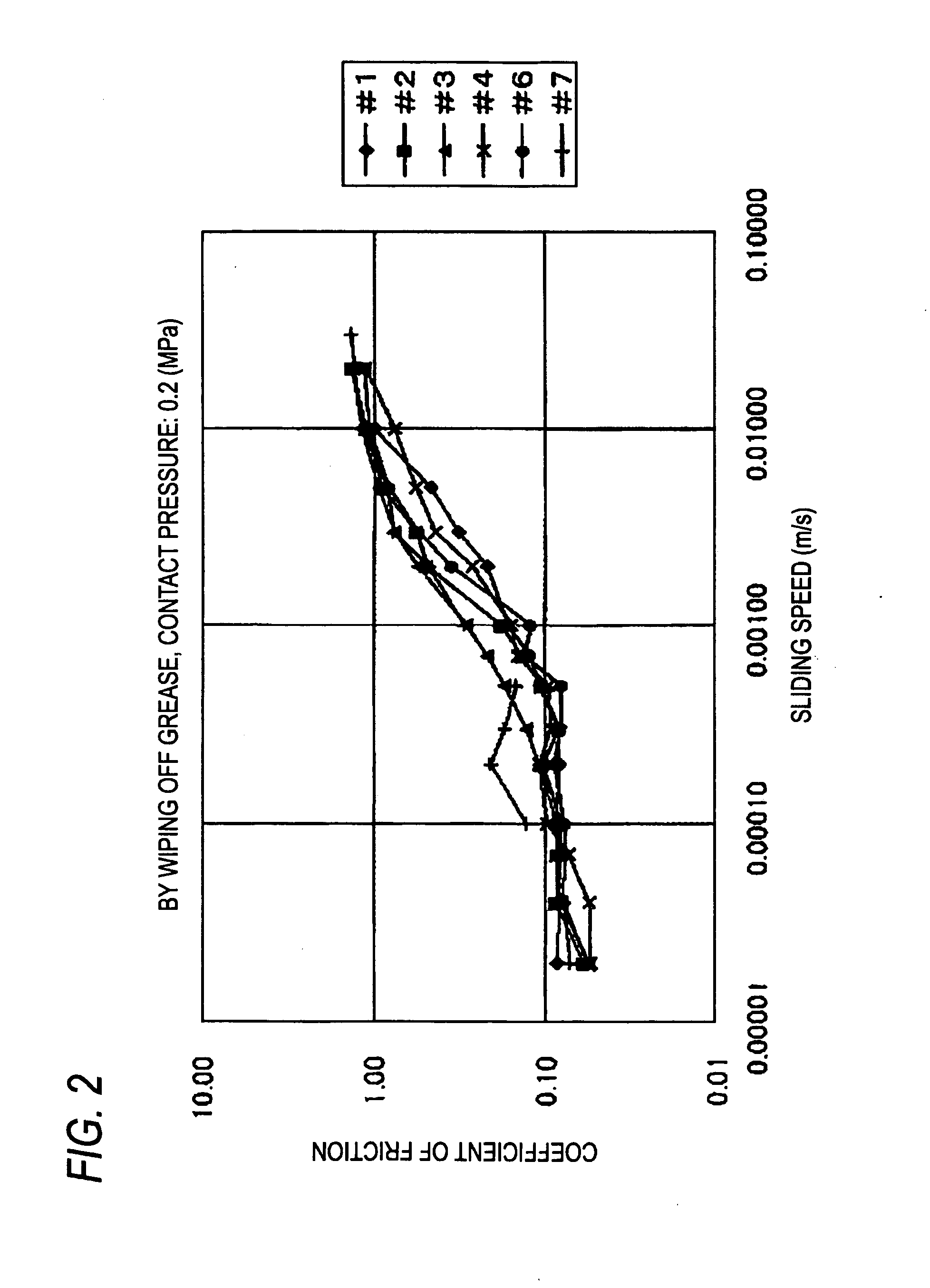
[0062]The rubber component, the metal soap, the organic acid amide and the oil-containing particle were kneaded, respectively in amounts shown in Table 8, and the obtained rubber composition was subjected to vulcanization and compression molding accompanied with heating into a prescribed shape, thereby preparing samples. As physical properties of each of the samples, a coefficient o...
experimental example
[0086]As the Experimental Example, 96.9 parts by mass of NBR [containing carbon black and graphite] as a rubber component, 0.1 parts by mass of lithium stearate [product number: S-7000, manufactured by Sakai Chemical Industry Co., Ltd.] as a metal soap, 1.0 part by mass of purified oleic acid amide [trade name: DIAMID 0-200, manufactured by Nippon Kasei Chemical Co., Ltd.] as an organic acid amide and 2.0 parts by mass of dimethylsilicone-supported silica (silicone compound) [trade name: TORAYFIL F-202, manufactured by Dow Corning Toray Co., Ltd. (oil content: 50 to 65% by mass, oil kinematic viscosity: about 60,000 cs, particle size: 10 to 100 μm)] as an oil-containing particle were kneaded to obtain a rubber composition which is corresponding to the rubber composition of Sample No. #52 of Example 2.
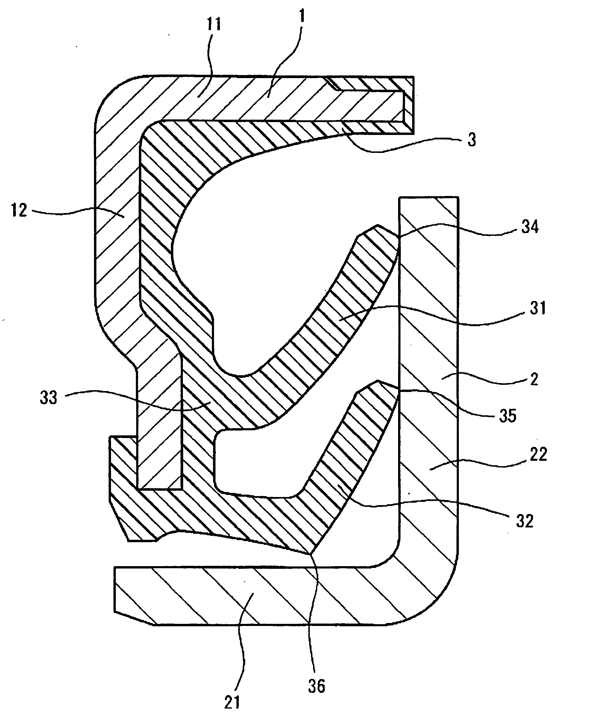
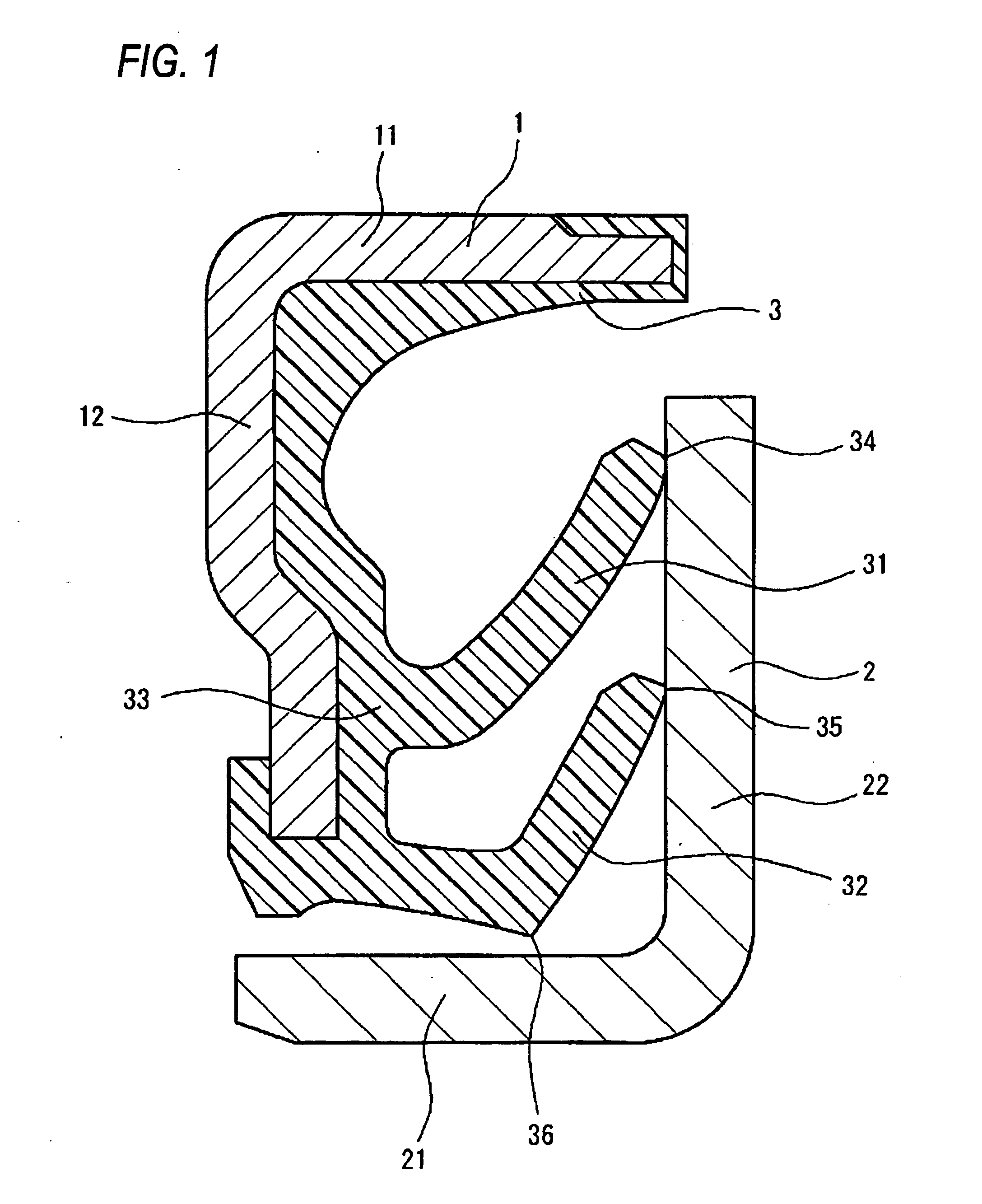
[0087]By using the thus obtained rubber composition, the elastic member (seal member) 3 having the shape shown in FIG. 1 was formed together with the first member 1 shown in FIG. 1 by m...
PUM
| Property | Measurement | Unit |
|---|---|---|
| Percent by mass | aaaaa | aaaaa |
| Percent by mass | aaaaa | aaaaa |
| Adhesion strength | aaaaa | aaaaa |
Abstract
Description
Claims
Application Information