Mode-locked fiber laser with improved life-time of saturable absorber

a fiber laser and life-time technology, applied in the direction of laser details, active medium shape and construction, electrical equipment, etc., can solve the problems of reducing the lifetime, reducing the lifetime, and reducing the life of the saturable absorber, so as to increase the spectral width of the pulse, increase the spectral width, and increase the optical power

Active Publication Date: 2010-11-25
NKT PHOTONICS
View PDF4 Cites 26 Cited by
  • Summary
  • Abstract
  • Description
  • Claims
  • Application Information

AI Technical Summary

Benefits of technology

[0011]A mode locked laser system according to the invention comprises a filter placed in the cavity, such as the end reflector of the cavity. The filter has spectral response arranged to penalize instability in the cavity. This effect is achieved by noticing that a pulse with an increased optical power (e.g. due to a thermal fluctuation) will experience a larger non-linearity in the cavity increasing the effect of self-phase modulation which in turn increases the spectral width of the pulse. As the pulse meets the filter, this is preferably arranged to filter away at least part of this broadening thus penalizing the fluctuation. Accordingly, in one embodiment the invention relates to a mode locked fiber laser system arranged to have a lasing bandwidth and a pulse peak power, said system having a linear cavity with a non-linear property, said cavity comprising a gain medium, a saturable absorber, and a filter having a spectral response, wherein the spectral response of said filter is arranged to reduce spectral components outside said lasing bandwidth arising from self-phase modulation caused by said non-linear property and an increase in pulse peak power.

Problems solved by technology

This in turn requires a high light intensity on the device, thus reducing the lifetime.
However, at some point mode locking is no longer possible, at which point the life time of the saturable absorber may be considered to have expired.
In some cases the saturable absorber becomes insensitive to the incoming optical power.
The saturable absorber may also expire instantly if the impingent optical power exceeds its damage threshold.
In many cases life times are in the order of hundreds of hours which is insufficient for most commercial applications of the laser.

Method used


Image

  • Mode-locked fiber laser with improved life-time of saturable absorber
  • Mode-locked fiber laser with improved life-time of saturable absorber
  • Mode-locked fiber laser with improved life-time of saturable absorber

Examples


Embodiment Construction

[0014]The invention will be explained more fully below with reference to the drawings in which:

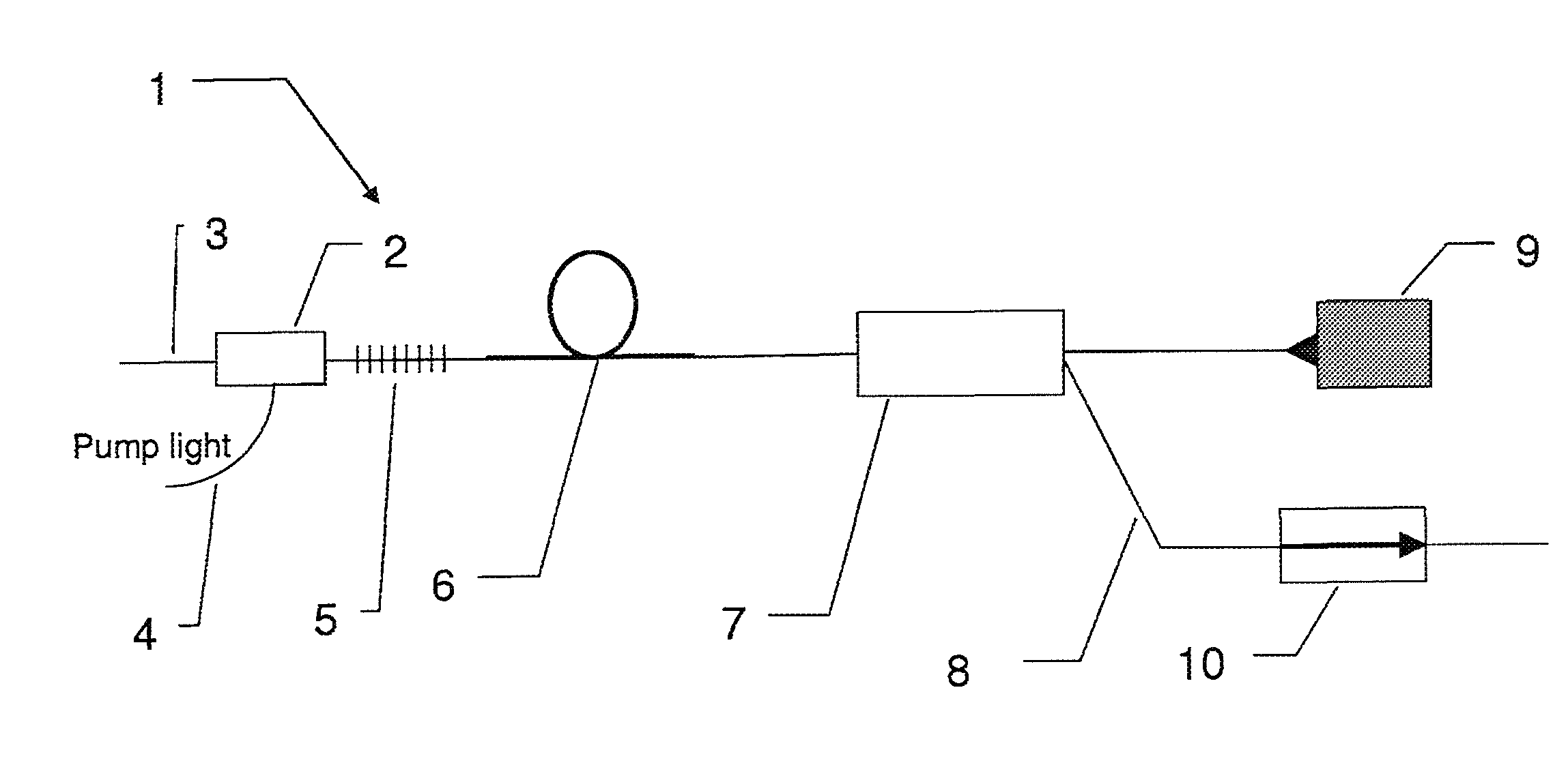
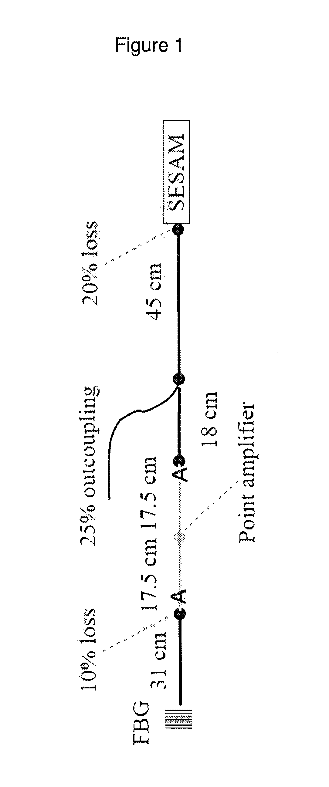
[0015]FIG. 1 shows a diagram of the laser model applied in the theoretical model discussed below. Laser amplification is modeled as a point amplification while SPM and dispersion is modeled via inserting a passive fiber with the appropriate values. The amplifier with Aeff=18 μm2 is laid out between the section of 31 cm and 18 cm, respectively. All other fibers are passive PM fibers with Aeff=43 μm2,

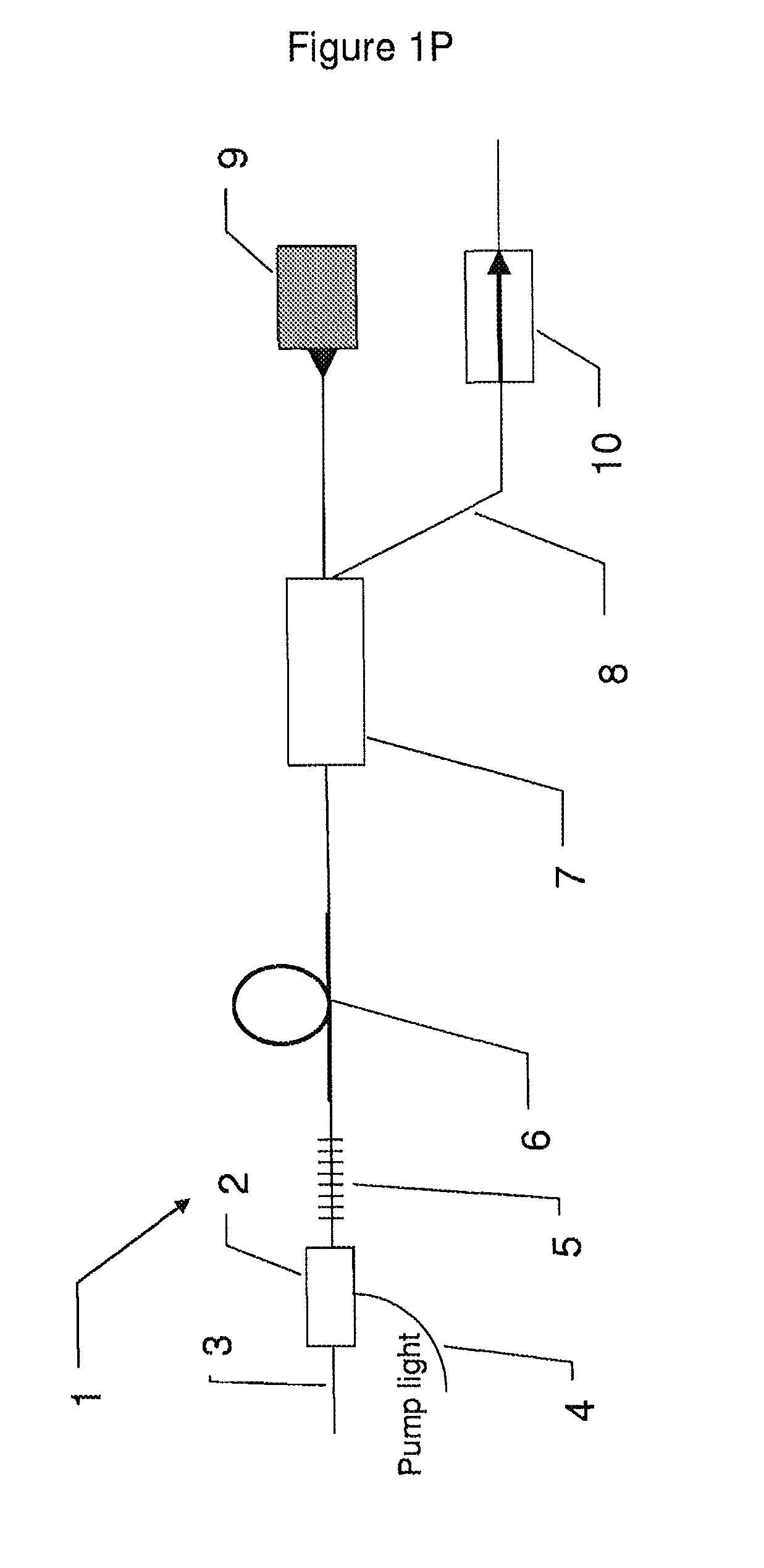
[0016]FIG. 1P shows an exemplary embodiment of a mode locked laser according to the invention,

[0017]FIG. 2 shows pulse (a) and chirp (b) profiles in the time domain of laser oscillators with the gratings BG3 and BG7 used as cavity end mirrors as calculated by the theoretical model.

[0018]FIG. 2P shows an exemplary embodiment of a mode locked laser according to the invention,

[0019]FIG. 3 shows dispersion curves (solid lines) of the BG3 and BG7 gratings. The grating reflectivity multiplied by 10 is...


PUM


Abstract

A mode locked fiber laser system is arranged to have a lasing bandwidth and having a linear cavity, the cavity including a gain medium, a saturable absorber having a saturation power, and a filter having a spectral response, wherein the mode locked fiber laser system is arranged so that substantial CW mode locked operation is obtainable with less than 3 times the saturation fluence impinging on the saturable absorber.

Description

[0001]The invention relates to a mode locked fiber laser system arranged to have a lasing bandwidth and having a linear cavity, said cavity comprising a gain medium, a saturable absorber having a saturation power, and filter having a spectral response.BACKGROUND[0002]Fiber based passively mode-locked ps lasers are of considerable interest as cheap and robust master oscillators for high-power ps and fs master-oscillator power amplifier (MOPA) systems. In particular, oscillators mode-locked by semiconductor saturable absorber mirrors (SESAMs) have been found to provide easy self-starting and good environmental stability. Considerable effort has recently been put into the development of Yb-based fiber oscillators capable of delivering high-quality self-similar pulses with a large bandwidth in both the ps and fs range.[0003]Apart from bandwidth and pulse quality, oscillators for practical use must also satisfy strict requirements on lifetime and stability. The latter is especially impor...

Claims


Application Information

Patent Timeline
Patent Type & Authority Applications(United States)
IPC IPC(8): H01S3/098H01S3/067
CPCH01S3/067H01S3/1118H01S3/08009
Inventor ANDERSEN, THOMAS VESTERGAARDLEICK, LASSELAEGSGAARD, JESPER
Owner NKT PHOTONICS
Why Eureka
Try Eureka