Road shape recognition device

a technology of shape recognition and road shape, which is applied in the direction of navigation instruments, anti-collision systems, controlling traffic signals, etc., can solve the problems of large processing load, difficult to apply this processing to an automatic control technique of the vehicle, and erroneous detection of vah, etc., and achieve the effect of more accurate and accurate generation

Active Publication Date: 2010-11-25
SUBARU CORP
View PDF4 Cites 60 Cited by
  • Summary
  • Abstract
  • Description
  • Claims
  • Application Information

AI Technical Summary

Benefits of technology

[0035]Thus, in the case of employing stereo matching as well, a road shape model can be generated more accurately according to the real road shape, and the advantages of the above aspects can be exhibited in a more accurate manner.

Problems solved by technology

However, processing load may be large when dividing a region in front of the vehicle into a great number of sections and performing linear approximation for each section.
However, as shown in FIG. 19B, in a situation in which the back portion of the preceding vehicle Vah exists on an extension of the flat road surface in front of the downhill B, at the time of performing linear approximation using the section R2, the distance data of the preceding vehicle Vah is not distinguished from the distance data of the road surface and is subjected to linear approximation, and consequently the preceding vehicle Vah may be erroneously detected as a road surface.
However, if processing thereof takes time, it is difficult to apply this processing to an automatic control technique of the vehicle, or the like.

Method used


Image

  • Road shape recognition device
  • Road shape recognition device
  • Road shape recognition device

Examples


first embodiment

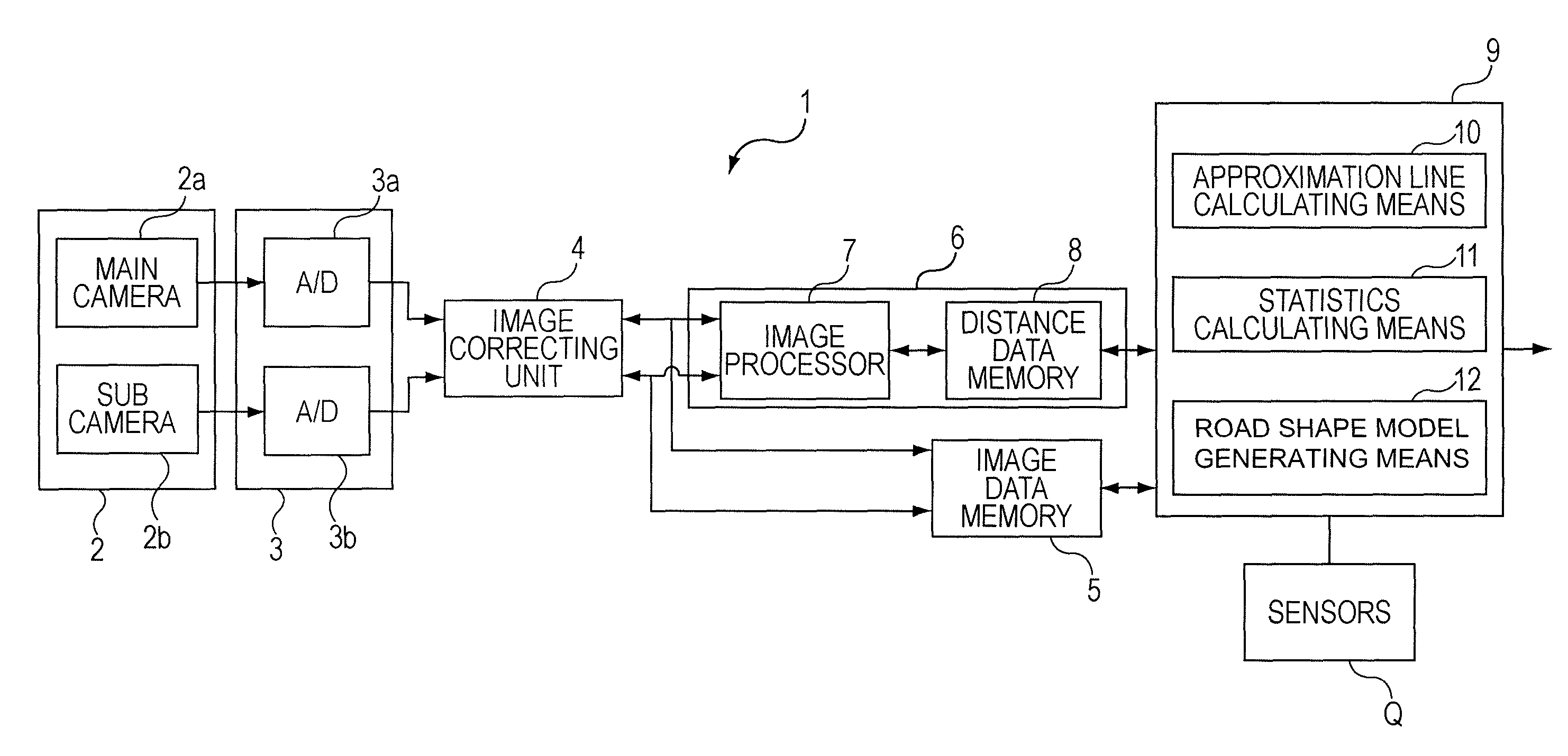
[0056]As shown in FIG. 1, a road shape recognition device 1 according to a first embodiment is configured of a processing unit 9 including image capturing means 2, distance and height detecting means 6, approximation line calculating means 10, statistics calculating means 11, and road shape model generating means 12, and so forth.

[0057]Note that the configuration of the upstream side of the processing unit 9 including the distance and height detecting means 6 and so forth is described in detail in JP-A Nos. 1994-266828 and 2001-092970, and so forth previously submitted by the present assignee, and see these publications for the detailed description of the configuration thereof. Brief description thereof will be made below.

[0058]According to the present embodiment, the image capturing means 2 is a stereo camera consisting of a main camera 2a on a driver side and a sub camera 2b on a front passenger sheet side which are attached near a room mirror of a vehicle at a predetermined dista...

second embodiment

[0116]With the above first embodiment, description has been made for calculating the approximation lines L1 and L2 with all of the distance data D of which at least the distance Z and height Y in real space have been detected by the distance and height detecting means 6, or distance data D of those included in a predetermined range from the position of a road shape model at a current sampling cycle estimated from the past sampling cycles and a subsequent behavior of the vehicle, and so forth.

[0117]However, the road shape model may be generated by detecting a marking such as a lane line lateral to the vehicle, and further, a numeral representing the legal speed limit displayed on a road surface, an arrow indicating the traveling direction, and using the distance data D corresponding to the detected marking. With the second embodiment, a road shape recognition device thus configured will be described.

[0118]As shown in FIG. 9, a road shape recognition device 20 according to the second ...


PUM


Abstract

A road shape recognition device includes: distance and height detecting means for detecting distance data having a distance and height in real space regarding a road surface where a vehicle is traveling at multiple mutually different points; approximation line calculating means for dividing the plurality of distance data into near and far groups as viewed from the vehicle to calculate an approximation line of the distance data for each group each time the distance data of the boundary portion between the two groups is transferred from one of the groups to the other; statistics calculating means for calculating statistics from the corresponding approximation line for each group where the distance data is transferred; and road shape model generating means for selecting one out of combinations of the approximation lines to generate a road shape model using the selected combination.

Description

CROSS-REFERENCE TO RELATED APPLICATIONS[0001]The present application claims priority from Japanese Patent Application No. 2009-123742 filed on May 22, 2009, and is hereby incorporated by reference in its entirety.BACKGROUND OF THE INVENTION[0002]1. Field of the Invention[0003]The present invention relates to road shape recognition devices, and specifically relates to a road shape recognition device which generates a road shape model based on distance data obtained by distance and height detecting means.[0004]2. Description of the Related Art[0005]In recent years, development of road shape recognition devices has been underway, in which an image capturing device such as a Charge Coupled Device (CCD) camera and Complementary Metal Oxide Semiconductor (CMOS) camera, or a laser radar distance measuring device, is mounted on a vehicle, and a road shape where the vehicle equipped with such a device is traveling is recognized by image analysis of an image captured with the image capturing ...

Claims


Application Information

Patent Timeline
Patent Type & Authority Applications(United States)
IPC IPC(8): G06F17/50G06K9/00G06F17/10B60R21/00G01B11/00G06T1/00G06T7/00G06T7/60G08G1/16
CPCB60W40/072B60W40/076G01S11/12Y02T10/82G06T7/0083G06T2207/10012G06T2207/30252G06K9/00798G06T7/12G06V20/588
Inventor SAITO, TORU
Owner SUBARU CORP
Why Eureka
Try Eureka