Geothermal electricity production methods and geothermal energy collection systems

a technology of geothermal energy and electricity production method, which is applied in the direction of mechanical power devices, mechanical equipment, machines/engines, etc., can solve the problems of large-scale implementation of solar collector fields or wind turbine fields at great cost, affecting the environment, and affecting the efficiency of electricity production

Active Publication Date: 2010-12-02
ELI ZADOK
View PDF4 Cites 19 Cited by
  • Summary
  • Abstract
  • Description
  • Claims
  • Application Information

AI Technical Summary

Benefits of technology

[0052]Two Devices, a System and two Methods are hereby invented to conductively harness and make available within a closed loop, through a combination of pumped, gravity driven and convective steam and / or fluid flow “renewable and sustainable” heat energy obtained from hot geologic rock strata, geothermal reservoirs or any other subterranean heat source for the purpose of directly performing useful work or for converting such harnessed heat energy to some other form of useful energy, such as electricity. The methods, system and devices eliminate entirely the need for any direct contact with or exposure to geothermal fluids, gases or any other potentially contaminated material.

Problems solved by technology

It should be noted that other so called “green” or “clean” alternative technologies tend to have practical limitations.
Pollution is therefore not eliminated and if employed on a large scale demand will drive the cost of electricity to unreasonable levels given current technological limitations.
Large scale implementation of solar collector fields or wind turbine fields will at great cost exert their own environmental impacts, which are at this point undetermined.
Additionally, there is the unreliability factor in that the wind doesn't always blow and the sun doesn't always shine and certainly doesn't shine at night.
Hydrogen powered vehicles are an exciting alternative, but the large volume of fuel storage required per vehicle makes them impractical at present.
Natural gas powered vehicles are a good stop gap, but natural gas is not renewable, it's expensive and burning it does contribute to so-called green house gases.
Ethanol fuels on any large scale are an environmental and economic disaster worse than gasoline or diesel fuel.
Ethanol production is already causing food shortages, which will only worsen as production is increased.
This alternative has not, unfortunately, been without its own issues and costs.
To harness this heat energy at useful temperatures, say higher than 150° C. under normal crust conditions requires drilling to great depth with a significant cost of investment.
To reach below ground temperatures of 300° C. to 400° C. is even more costly.
After using, the water may be re-circulated back to the reservoir to mine more heat or may be wasted.
These patents clearly demonstrate the types of difficulties encountered in attempting to mine geothermal heat energy.
Unfortunately, many, if not most of these formations are found in tectonically active locations, some of which may experience significant faulting along with earthquake activity and in the case of active volcanoes, may experience flows of molten igneous material or airborne ash and debris.
Applying the above mentioned technology inappropriately within such a tectonically active area would be unsafe and from an investment standpoint would have to be characterized as high risk.
Another significant and potentially costly issue involves the direct use of geothermal fluids as is typical today.
Geothermal fluids can be highly corrosive and the direct use thereof can be damaging to equipment.
The direct use of fluids pumped from geothermal reservoirs has been costly from an anti-corrosion standpoint, but perhaps even more so by limitations as to actual extent of “renewability”, which in some ways becomes the most significant issue regarding future investment in geothermal energy.
There are, however, serious limitations on the rate at which these insitu fluids can be removed from the reservoir and replenished.
If geothermal fluid is removed from the reservoir at a rate higher than that at which the aquifer can recharge itself; the fluid level within the reservoir will drop over time, resulting in a necessary increase in pumping cost at the least and in the worse case a diminishment of the resource for useful purposes.
This has been an expensive solution.
This has been a successful method, but has raised serious questions regarding potential long term environmental effects of artificially injecting large quantities of water into what has historically been dry rock strata.
The list of problems historically associated with the use and harvesting of geothermal energy sources is not particularly long.
It is none-the-less a serious list posing rather costly solutions.
Uncertainty with regard to future reservoir levels means uncertainty with regard to future electricity production, which means uncertainty with regard to future revenue, which in turn means increased risk of investment.
One last complication regarding direct use of geothermal fluids is environmental.
Vaporization of these geothermal fluids to drive a steam turbine and subsequent condensation back to liquid tends to bring contaminants out of solution.
The direct discharge of this untreated brine back into the reservoir or to a local river or lake can result in environmental pollution.
Treatment of this brine then becomes an additional cost.
Direct discharge of un-cooled geothermal brines to a lake or river can result in thermal pollution.
This is serious as an increase as small as 4° C. within a water course can be fatal to many fish and harmful to aquatic plants.
In either case both treatment and cooling of vast quantities of geothermal fluid add significantly to the cost of electricity production by existing geothermal means.
Added cost is always added financial risk.

Method used


Image

  • Geothermal electricity production methods and geothermal energy collection systems
  • Geothermal electricity production methods and geothermal energy collection systems
  • Geothermal electricity production methods and geothermal energy collection systems

Examples


Embodiment Construction

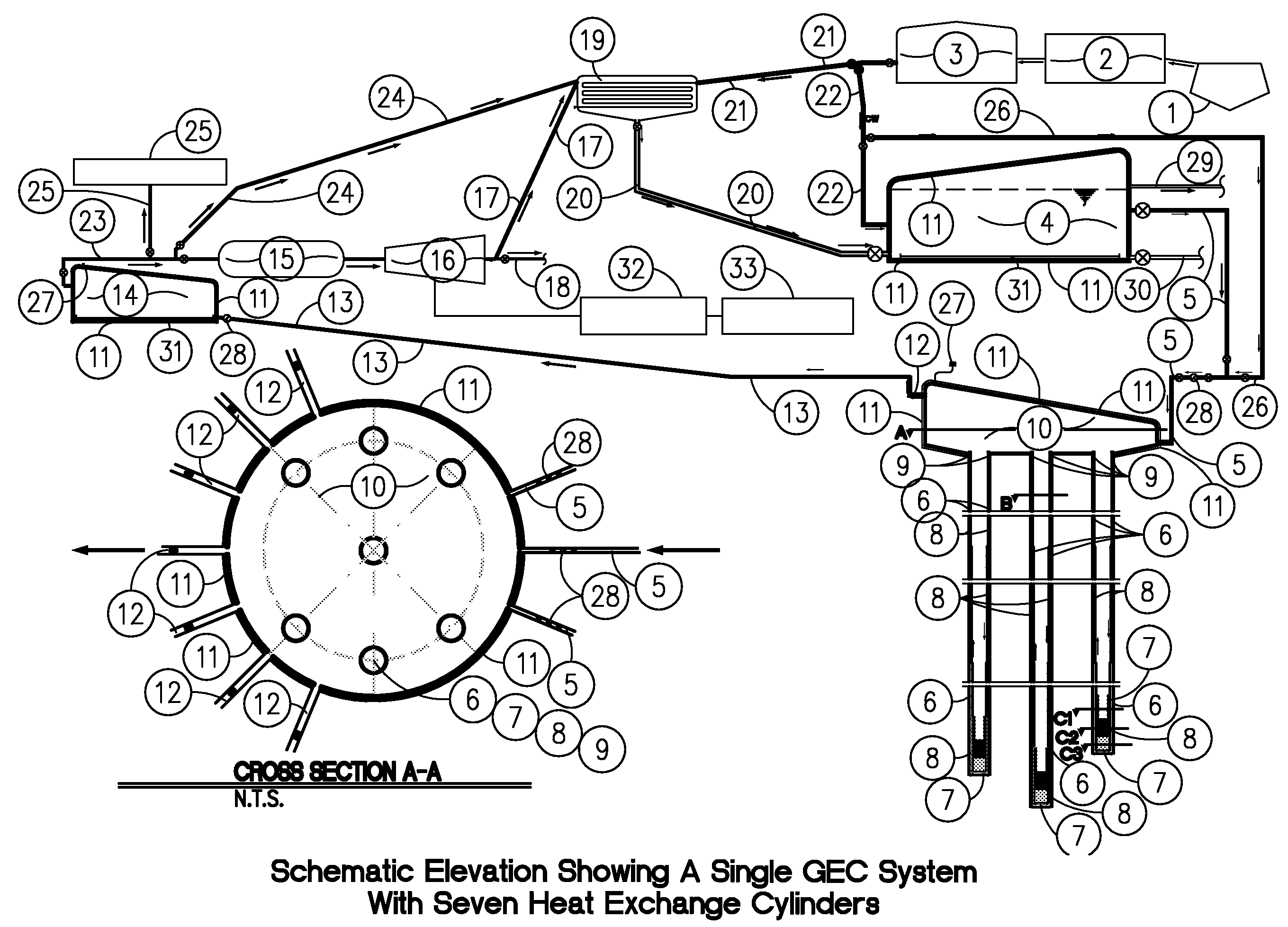
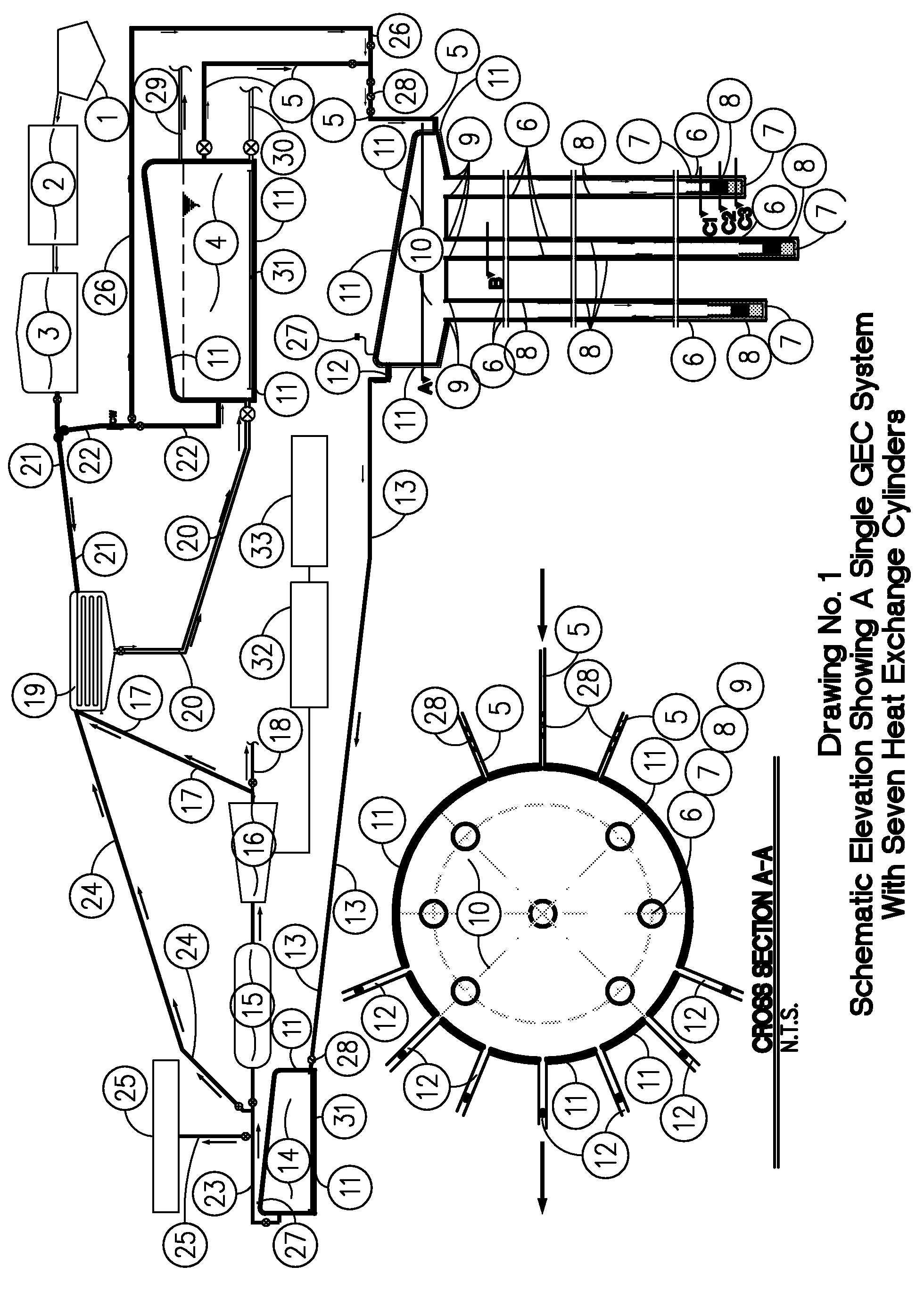
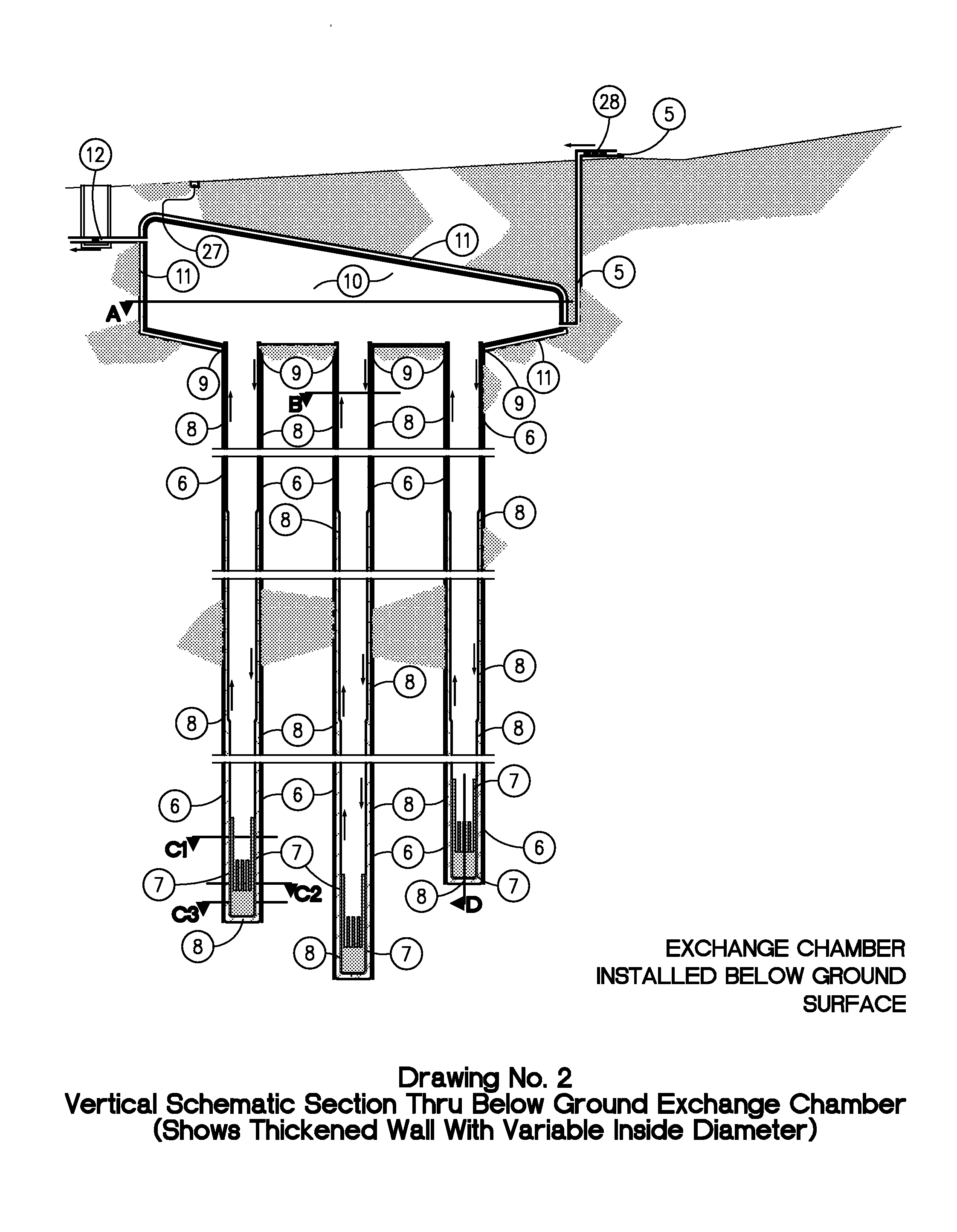
[0088]This invention, the GEOTHERMAL ENERGY COLLECTOR (GEC) 6, 7, 8, 9, 10; the GEOTHERMAL ENERGY EXCHANGER (GEE) 6, 7, 8, 9, 35 along with the GEOTHERMAL FLUID HEATING OR STEAM PRODUCTION SYSTEM; the GEOTHERMAL ELECTRICITY PRODUCTION METHOD; the GEOTHERMAL HEAT ENERGY METHOD and their use as shown in Drawings 1, 15, 23, 24, 25, 26 and 27 appropriately employed along with existing technologies and equipment, altogether comprising “the methods” allows any suitable, isolated and confined fluid, such as treated water, water modified by additives and / or catalysts or steam to be supplied 5, circulated below ground and conductively heated within the heat exchange cylinders 8; then to be discharged 12 providing steam to steam turbines 16 or heated fluid for some other use 25; then to be condensed 19 if necessary and returned or recirculated 20 back to the mixing container 4 for reuse within an enclosed, non-polluting system. Within the preferred embodiment fluid, vapor and / or steam flows a...


PUM


Abstract

Two Geothermal energy harnessing devices, steam producing System, electricity production Method and heat energy Method are invented for mining renewable geothermal heat energy within a non-polluting, re-circulating, closed cycle intended for electricity generating applications or for other direct or indirect heat uses. The devices, the “Geothermal Energy Collector” and the “Geothermal Energy Exchanger” can work with a Depressurized Mixing Container and a Pressurized Storage Container the entirety of which comprises “THE GEOTHERMAL FLUID HEATING OR STEAM PRODUCTION SYSTEM. The system serves other equipment, such as a phase separator, steam turbine, generator and condenser, which working together with the system comprises either “THE GEOTHERMAL ELECTRICITY PRODUCTION METHOD” or “THE GEOTHERMAL HEAT ENERGY METHOD”. The GEC or GEE can work alone or within a system to add heat to any fluid and to use the heated fluid to supplement any appropriate technology, to produce electricity or for other direct or indirect uses.

Description

BACKGROUND OF THE INVENTION[0001]Geothermal energy is defined as “heat from the earth”. The earth's heat is a “renewable resource” as defined by The National Energy Policy Act of 1992 and the Pacific Northwest Electric Power Planning and Conservation Act of 1980 and is estimated by the U.S. Geothermal Industry for the Renewable Energy Task Force (1997) to be “equivalent to 42 million megawatts of power”.[0002]The potential for using heat energy found within the earth, sometimes referred to as “heat mining”; either for direct use or for generation of electricity has been a subject of significant interest over the years. If heat mining could be efficiently and safely employed, geothermal resources could represent a nearly inexhaustible source of non-fossil, non-nuclear fuel.[0003]It should be noted that other so called “green” or “clean” alternative technologies tend to have practical limitations. Electrically powered vehicles currently require electricity for recharging to be generat...

Claims


Application Information

Patent Timeline
Patent Type & Authority Applications(United States)
IPC IPC(8): F03G7/00
CPCF03G7/00
Inventor ELI, ZADOKKOLINSKI, BRUCE J.
Owner ELI ZADOK
Why Eureka
Try Eureka