Refrigerant distribution device for refrigeration system

a technology of refrigerant distribution and refrigeration system, which is applied in the direction of domestic cooling apparatus, lighting and heating apparatus, support, etc., can solve the problem of difficult to make a uniform mixture in the principal distributor b>1

Inactive Publication Date: 2010-12-02
JOHNSON CONTROLS TECH CO +1
View PDF44 Cites 2 Cited by
  • Summary
  • Abstract
  • Description
  • Claims
  • Application Information

AI Technical Summary

Benefits of technology

[0007]A series of concepts with simplified form are referenced in the invention content, which will be further described in detail in the part of particular embodiments. The invention content of the present invention does not imply to attempt to limit the critical features and the essential technical features of the solution which it seeks to protect, furthermore, does not imply to attempt to ensure the protection scope of technical solution which it seeks to protect.

Problems solved by technology

Because gas refrigerant and liquid refrigerant have different densities and distributions, it is difficult to make a uniform mixture in the principal distributor 1.

Method used


Image

  • Refrigerant distribution device for refrigeration system
  • Refrigerant distribution device for refrigeration system
  • Refrigerant distribution device for refrigeration system

Examples


first embodiment

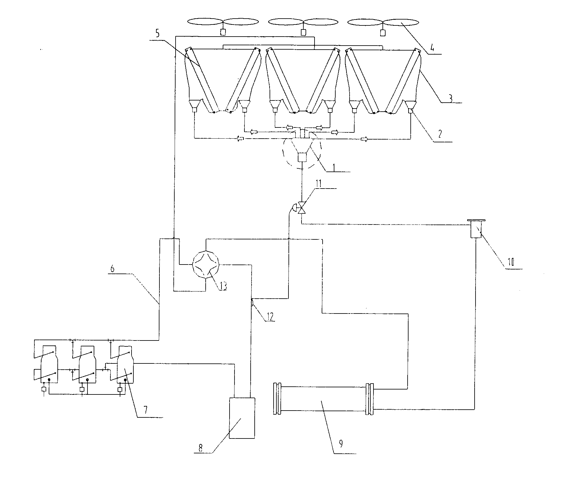
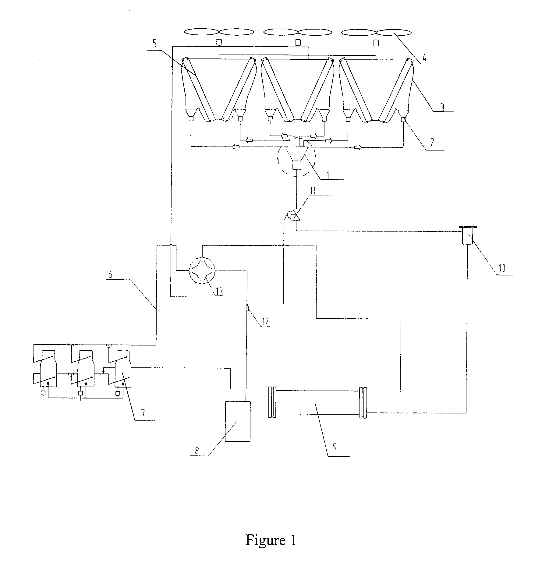
[0046]FIG. 2 is a structural schematic diagram of the refrigerant distribution device in principal distributor for refrigeration system in accordance with the present invention. As shown in FIG. 2, the refrigerant distribution device 1, along the refrigerant's flowing direction, successively comprises: a refrigerant entering duct 1_1, a bottom cover plate 1_2, a core 1_3, a cylinder 1_4, an upper cover plate 1_5 and multi-branch ducts 1_6. The refrigerant as shown in FIG. 1 is throttled by the thermal expansion valve 11, forms two phases state of gas and liquid, and enters into the distribution device 1 via the entering duct 1_1 of the refrigerant distribution device 1. After impacting with the core 1_3 of the refrigerant distribution device 1 and being throttled, the refrigerant of two phases of gas-liquid is mixed fully and uniformly in the distribution device 1, then flows out from the distribution device 1 by the upper cover plate 1_5 and the multi-branch ducts 1_6, and into the...

second embodiment

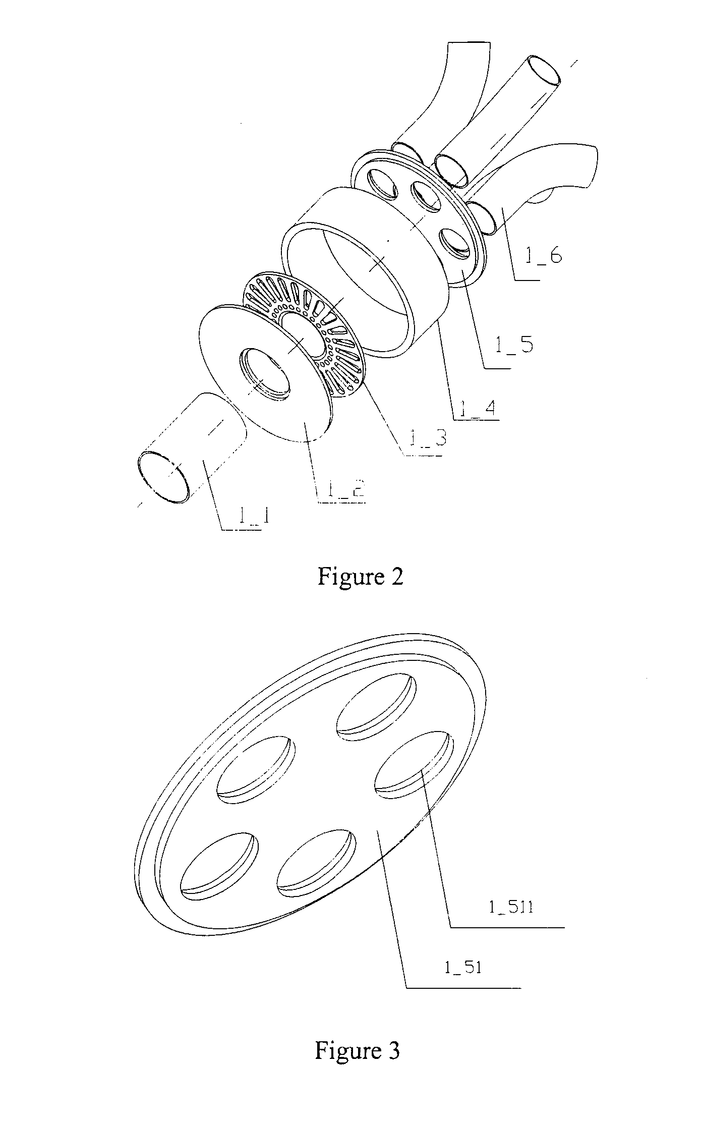
[0049]FIG. 4a and FIG. 4b are structural schematic diagrams of the upper cover plate of the refrigerant distribution device shown in FIG. 2, wherein FIG. 4b is a sectional view along the central line of FIG. 4a. As shown in FIGS. 4a and 4b, the upper cover plate 1_52 having a centrosymmetric shape is provided with an upper cover plate protuberance 1_522 on its central area, a plurality of (more than two) second openings 1_521 corresponding to the duct orifices of said multi-branch ducts 1_6 distributed around the protuberance 1_522, the second openings 1_521 connecting with the multi-branch ducts 1_6. The upper cover plate protuberance 1_522 protuberates to the multi-branch ducts 1_6, whose size and shape are disposed in line with the distribution state of the orifices of the multi-branch ducts 1_6. The upper cover plate protuberance 1_522 makes a certain improvement for impacting effect and throttling effect of two phases refrigerant fluid, and enhances the uniformity of the princi...

third embodiment

[0053]FIG. 11 is a structural schematic diagram of the core of the refrigerant distribution device in FIG. 2. As shown in FIG. 11, the core 1_33 is a circular flat plate; a protuberated ellipsoidal crown 1_333 is provided at the central part; a plurality of circular first openings 1_332 are uniformly distributed along the circumferential equal angles of the spherical crown 1_333; also uniformly distributed are square first openings 1_331 along the equal angles of the circumference of the circular flat plate with the radial direction. When the refrigerant entering through the entering duct 1_1 of distribution device 1 impacts the spherical crown 1_333, the liquid droplets included in the refrigerant break into small droplets; the gas and liquid simultaneously change the direction; by the throttling of the uniformly distributed circular first openings 1_332, the gas-liquid mixture becomes the refrigerant mixture with more uniform thinning droplets; a part of gas-liquid mixture enters ...


PUM


Abstract

The invention provides a refrigerant distribution device for refrigeration system which is capable of improving heat exchange efficiency, comprising: an entering duct, a bottom cover plate, a core, a hollow cylinder, an upper cover plate and multi-branch ducts. The core is disposed in the space formed by the bottom cover plate, the cylinder and the upper cover plate, wherein a plurality of openings are distributed on the core. The refrigerant distribution device according to the invention is capable of realizing uniform distribution and allocation of refrigerant in refrigeration system, and improving heat exchange efficiency of the refrigeration system.

Description

CROSS-REFERENCE TO RELATED APPLICATION[0001]This patent application claims priority to Chinese Patent Application No. 200910143947.7 filed Jun. 2, 2009.FIELD OF THE INVENTION[0002]The invention relates to a fluid distribution device, particularly relates to a refrigerant distribution device utilized in refrigeration system.BACKGROUND OF THE INVENTION[0003]To improve the heat exchange efficiency of refrigeration system, refrigerant distribution device is broadly used in prior refrigeration systems. As shown in FIG. 1, it is a conventional heat pump air-conditioning system. The system mainly comprises following components: a compressor 7, a duct 6, a four-way reversing valve 13, a multipieces (more than two pieces) heat exchanger 5, a fan 4, a small distributor 2, a capillary 3, a principal distributor 1, a thermal expansion valve 11, a temperature sensing bulb 12, a drier filter 10, a heat exchanger 9 and a gas-liquid separator 8.[0004]When the units operate at the heat pump conditio...

Claims


Application Information

Patent Timeline
Patent Type & Authority Applications(United States)
IPC IPC(8): F25D25/00
CPCF25B39/028F25B2500/18F25B41/00
Inventor REN, NENGWANG, LISU, XIUPING
Owner JOHNSON CONTROLS TECH CO
Why Eureka
Try Eureka