Method for wax removal and measurement of wax thickness

a technology of measurement method and wax removal, applied in the direction of instruments, cleaning using liquids, borehole/well accessories, etc., can solve the problems of reducing the cross-sectional area of the pipeline, affecting the installation and operation of the pipeline, and accumulating wax at the inside wall of the pipeline. , to achieve the effect of cost-effective installation and operation

Active Publication Date: 2010-12-02
DEN NORSKE STATS OLJESELSKAP AS
View PDF8 Cites 21 Cited by
  • Summary
  • Abstract
  • Description
  • Claims
  • Application Information

AI Technical Summary

Benefits of technology

[0015]The intention of the present invention is to provide a new method for removal of wax deposits that is cost efficient both to install and operate, which is a...

Problems solved by technology

Wax deposition at the inside wall of oil pipelines is a severe problem in today's oil production infrastructure: When warm oil flows through a pipeline with cold walls, wax will precipitate and adhere to the walls.
This in turn will reduce the pipeline cross-sectional area leading without proper counter measures, to a loss of pressure, and ultimately to a complete blockage of the pipeline.
Pigging is a complex and expensive operation.
It is also a risky operation, as of today; there is no secure way of measuring/predicting the amount of wax deposited in the pipeline.
This induces the risk that more wax is deposited than the pig diameter is designed for, resulting in a stuck pig.
Chemical inhibition is expensive due to the fact that an additional pipeline has to be ...

Method used


Image

  • Method for wax removal and measurement of wax thickness
  • Method for wax removal and measurement of wax thickness
  • Method for wax removal and measurement of wax thickness

Examples


example 1

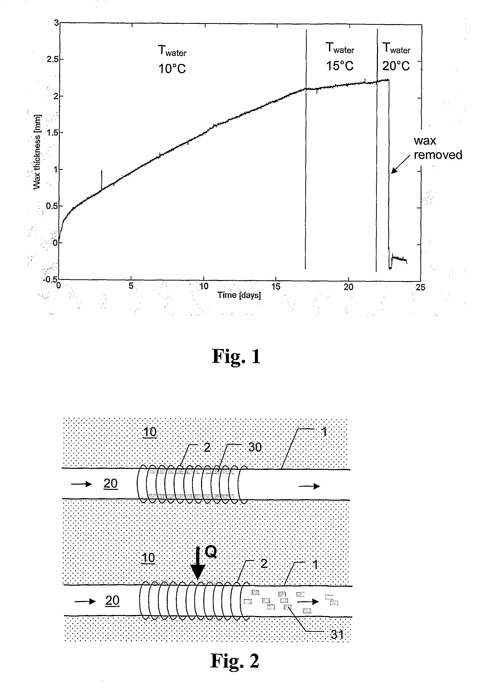
[0065]FIG. 1 shows the results from an experiment in a wax rig at StatoilHydro Research Centre, Porsgrunn, Norway: A waxy condensate is circulated at constant temperature (20° C.) through a rig. The rig is cooled from the outside by a water annulus.

[0066]During the first 17 days, the water in the annulus was at 10° C., stimulating a continuous build-up of wax in the rig.

[0067]After 17 days the water temperature was increased to 15° C. so that the temperature difference between condensate / water was reduced. This made the wax-build-up slower.

[0068]After 22 days the water temperature was increased to 20° C. so that the temperature between water and condensate was the same. After 1 day the wax that was previously deposited suddenly loosened and was transported downstream with the condensate. After stopping and opening the rig it was found to be clean without any wax at the walls.

[0069]An explanation for the loosening is that, while increasing the wall temperature the wax structure near ...

example 2

Saturn Cold Flow

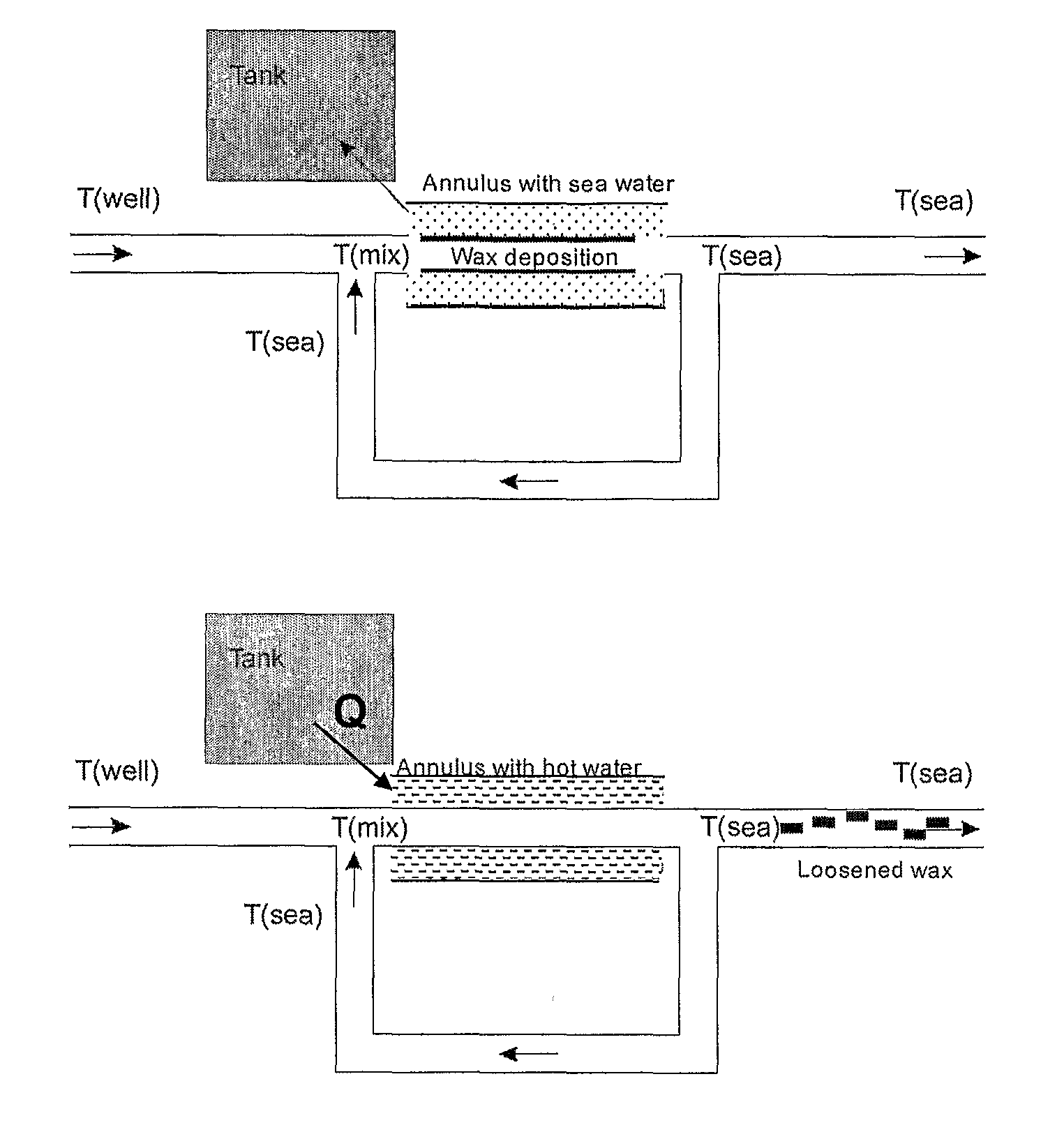
[0072]The Saturn technology is, in short, a technique based on the idea that dry hydrate and wax particles can be transportable and non-agglomerating during flow and shut-down conditions, further described in WO 2004 / 059178. By recirculating a cold slip-stream of hydrocarbon fluids with hydrate / wax particles into the hot well stream as shown in FIG. 4, dry hydrate / wax particles should form by ‘crash-cooling’ as slurry particles in the bulk in a reaction zone in stead of precipitating on the wall, and the fluids are cooled to ambient temperature in the vicinity of the reaction zone. Hence no deposition on pipe walls and blockage should occur when the slurry particles are further transported with gas and oil for long distances, after the splitter.

[0073]However, if the recirculated cold stream is to be mixed with the warm well stream close to the production manifold, to avoid wax deposition and hydrate formation during shut-downs, the temperature close to the mixing poi...

example 3

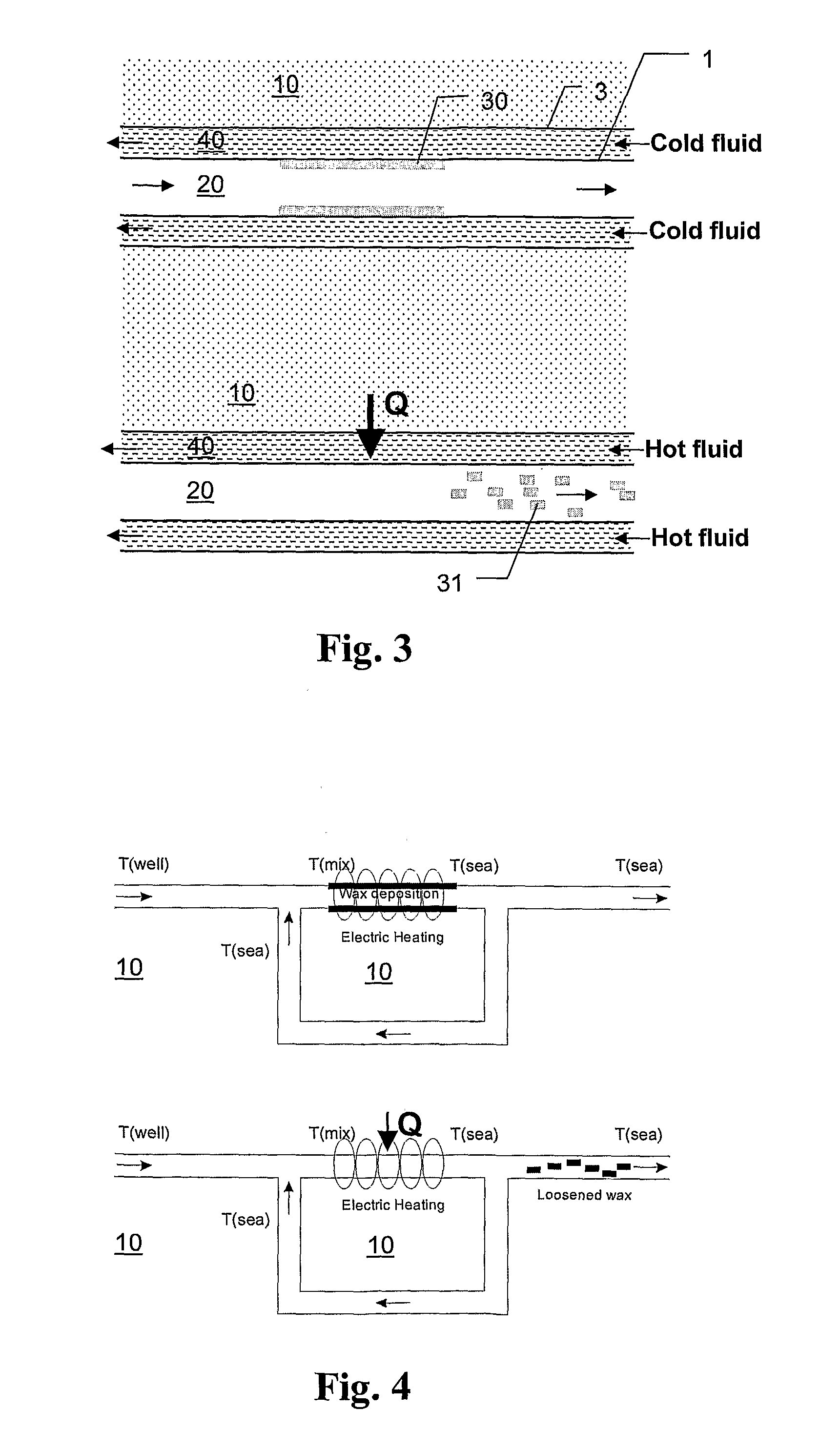
[0088]This principle has been proven in a wax rig, reference being made to FIGS. 11 and 12.

[0089]The heat pulse may be for example applied by an electric heating cable that is switched on for a short time or by a water annulus that is flooded with hot water for a short time. In the experiment shown in FIGS. 11 and 12, a temperature difference of only 10° C. between the oil and the water in the annulus was sufficient to provide reasonable results.

[0090]In this experiment, the temperatures were measured directly in the oil bulk flow. This is not desirable in a production environment. An alternative would be to measure the (outer) pipe wall temperature which provides the same information as shown in FIG. 12. In the alternative case of using hot water in an annulus, it is also possible to monitor the water temperature and the temperature drop from inlet to outlet during the heat pulse, as shown in FIG. 10.

[0091]Experiment performed in Wax Rig: Oil is circulated for one week at constant ...


PUM


Abstract

A method for removal of wax deposited on an inner wall in contact with a fluid stream. The method includes the steps of cooling the inner wall and the fluid stream to a temperature of or below the wax appearance temperature, enabling wax to dissolve and precipitate on the inner wall, and heating of the inner wall for a short period of time to release the deposited wax from the surface of the inner wall, mainly in the form of solid parts. The thickness of wax deposits in a pipe section can be determined by computing the temperatures obtained upstream and downstream in the said pipe section, before and after applying heat pulse.

Description

PRIORITY CLAIM[0001]The present application is a National Phase Entry of PCT Application No. PCT / NO2008 / 000371, filed Oct. 20, 2008, which claims priority to Norway Application Number 20075366, filed Oct. 19, 2007, the disclosures of which are hereby incorporated by reference herein in their entirety.[0002]The present invention relates to a method for removal of solids that build-up in a system or conduit containing or conveying fluid. Especially, the present invention relates to a method for removal of wax from pipelines and other equipment used for the transport of hydrocarbons.BACKGROUND OF THE INVENTION[0003]Wax deposition at the inside wall of oil pipelines is a severe problem in today's oil production infrastructure: When warm oil flows through a pipeline with cold walls, wax will precipitate and adhere to the walls. This in turn will reduce the pipeline cross-sectional area leading without proper counter measures, to a loss of pressure, and ultimately to a complete blockage o...

Claims


Application Information

Patent Timeline
IPC IPC(8): B08B9/04B08B7/00G01B11/06
CPCB08B9/027E21B43/01E21B36/00E21B37/00F28G13/005F28G15/003G01B21/085
Inventor HOFFMAN, RYANAMUNDSEN, LENE
Owner DEN NORSKE STATS OLJESELSKAP AS
Why Eureka
Try Eureka