Solenoid valve

Inactive Publication Date: 2010-12-02
ROBERT BOSCH GMBH
View PDF13 Cites 7 Cited by
  • Summary
  • Abstract
  • Description
  • Claims
  • Application Information

AI Technical Summary

Benefits of technology

[0005]The solenoid valve of the invention having the characteristics of independent claim 1 has the advantage that the stroke-dependent courses of the magnetic force, the spring force, and the fluid force are combined over the stroke course of the armature and of the closing element in such a way that between the closed position and the open position of the armature and of the closing element, at least one further stable operating point can be established, which represents a point of force equilibrium with a negative total force gradient. Because of the special selection of the courses o

Problems solved by technology

However, as a result the total force level also becomes quite high, which when current is supplied to the magnet assembly leads to high cur

Method used


Image

  • Solenoid valve
  • Solenoid valve
  • Solenoid valve

Examples


Embodiment Construction

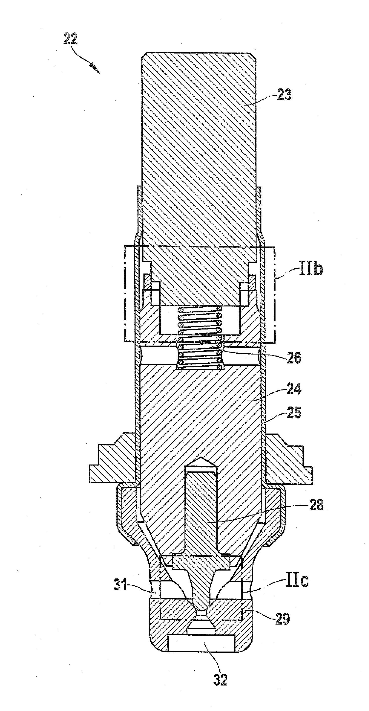
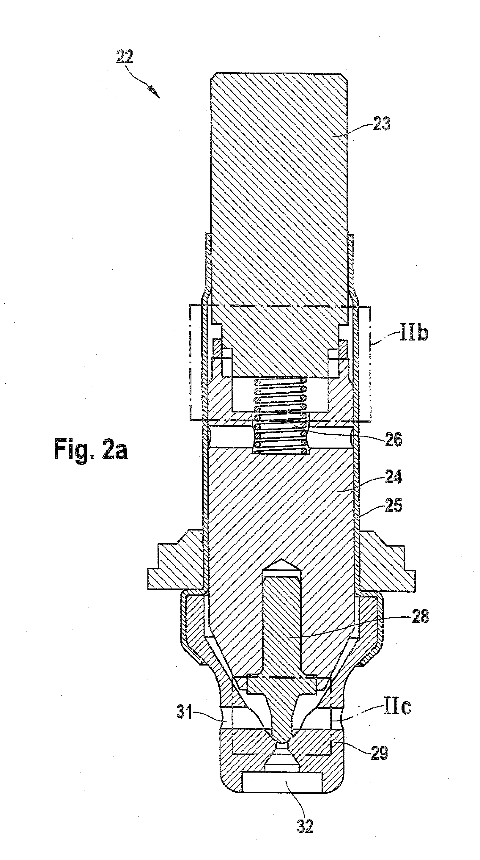
[0018]As can be seen from the graphs in FIG. 4, a conventional solenoid valve, valve 1, embodied as an on-off valve with a flow through it in the stroke-closing direction has the schematic courses shown in column 1 of the magnetic force Fmagnetic, the spring force Fspring, and the fluid force Fhydralic. A conventional solenoid valve, valve 2, embodied as a continuous valve with a flow through it in the stroke-opening direction has the schematic courses shown in column 2 of the magnetic force Fmagnet, the spring force Fspring, and the fluid force Fhydraulic. As can be seen from FIG. 3, the course of the force of the magnetic force Fmagnetic should be as flat as possible over the stroke. The restoring spring should be embodied as stiffly as possible; that is, the restoring spring 26 should have a high spring stiffness. The course of the fluid force Fhydraulic over the stroke should also be as flat as possible. The schematic courses of the magnetic force solenoid valve, the spring forc...


PUM


Abstract

The invention relates to a solenoid valve with a magnet assembly and a valve cartridge having a pole core, a valve insert connected to the pole core, an armature which is guided within the valve insert in an axially movable manner between a closed position and an open position and is coupled to a closing element, and a valve body which is connected to the valve insert and has a main valve seat which is arranged between at least one first flow opening and a second flow opening. The axially movable armature, when the magnet assembly is energized, is moved by a generated magnetic force within the valve insert in the direction of the pole core counter to a spring force of a resetting spring and counter to a fluid force in order to lift the closing element out of the main valve seat; and to permit a flow of fluid between the at least one first flow opening and the second flow opening. The axially movable armature is moved away from the pole core by the spring force of the restoring spring and by the fluid force within the valve insert in order to press the closing element into the main valve seat in a sealing manner and to interrupt the fluid flow between the at least one first flow opening and the second flow opening.

Description

PRIOR ART[0001]The invention relates to a solenoid valve as generically defined by the preamble to independent claim 1.[0002]A conventional solenoid valve, particularly for a hydraulic unit which is used for instance in an anti-lock brake system (ABS) or a traction control system (TC system) or an electronic stability program system (ESP system), is shown in FIG. 1. As can be seen from FIG. 1, a conventional solenoid valve 1, which is closed when without current and which is embodied as an on-off valve, includes a valve cartridge 2 and a magnet assembly 13. The valve cartridge 2 includes a pole core 3, a valve insert 5 connected to the pole core 3 and embodied as a sleeve, an armature 4 guided axially movably inside the valve insert 5 between a closed position and an open position, which armature is coupled with a closing element 8, and a valve body 9, connected to the valve insert 5, with a main valve seat 10 that is disposed between at least one first flow opening 11 and a second ...

Claims


Application Information

Patent Timeline
IPC IPC(8): F16K31/06
CPCB60T8/363F16K31/0665F16K31/0655
Inventor HEYER, KLAUSAMBROSI, MASSIMILIANOEISENLAUER, MICHAELRIETSCHE, MICHAELTISCHER, MICHAELSTEINGASS, STEPHANHILDEN, MICHAEL
Owner ROBERT BOSCH GMBH
Why Eureka
Try Eureka