
Wind turbine

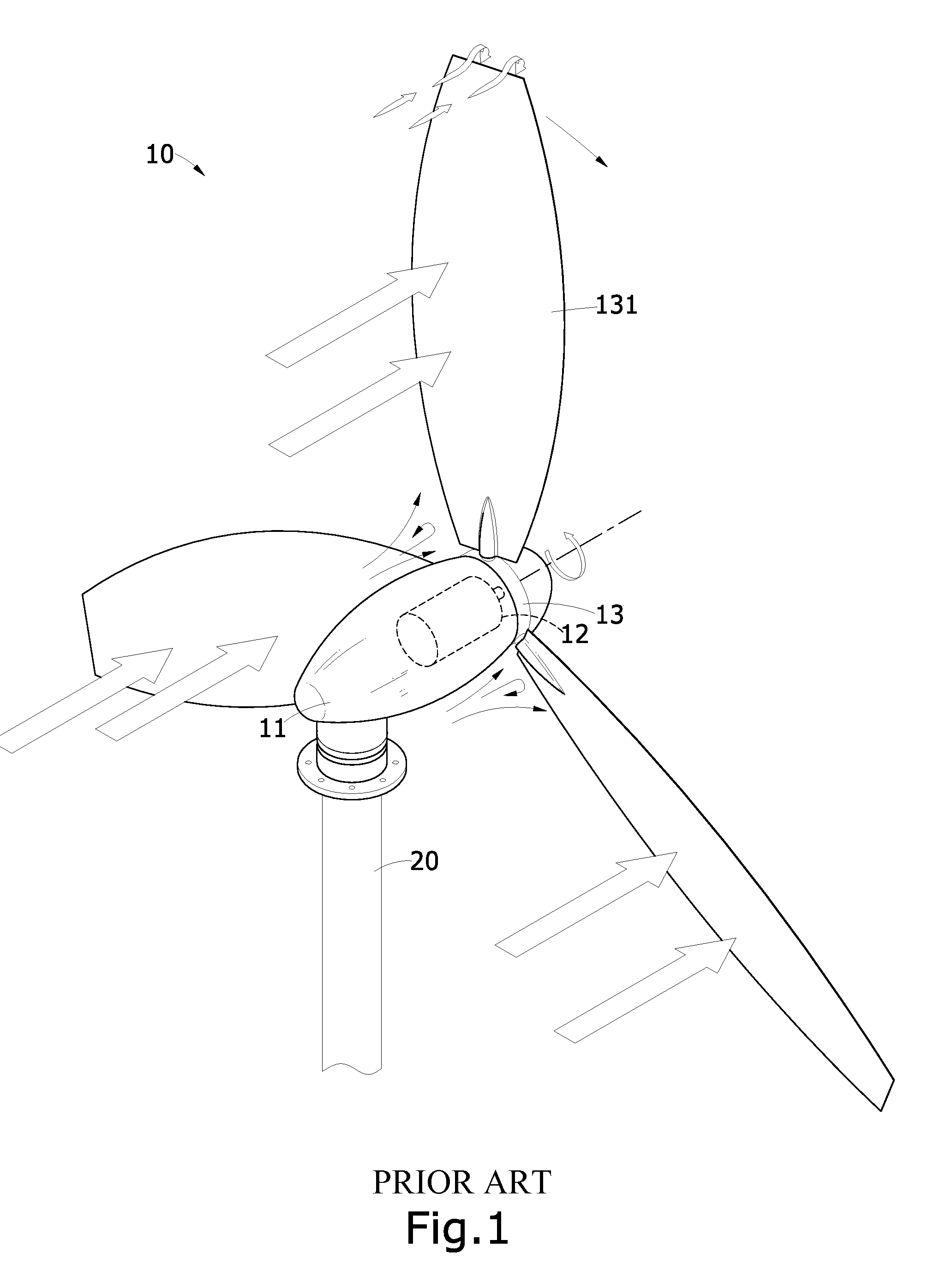
a wind turbine and turbine blade technology, applied in the direction of electric generator control, machines/engines, sustainable buildings, etc., can solve the problems of high cost of wind turbines of this type, achieve the effects of improving wind energy utilization efficiency, reducing turbulence, and increasing wind pressur

Inactive Publication Date: 2010-12-02
LEE JIA YUAN
View PDF8 Cites 11 Cited by
  • Summary
  • Abstract
  • Description
  • Claims
  • Application Information

AI Technical Summary

Benefits of technology

[0005]An objective of the present invention is to provide a nacelle structure of a wind turbine, which reduces the drag caused by turbulent flows and increases wind pressure so as to improve the utilization efficiency of wind energy.
[0007]A further objective of the present invention is to provide a wind turbine, which reduces the occurrence of tip vortex and wind noise generated by the rotation of a vane wheel, so as to improve the utilization efficiency of wind energy.
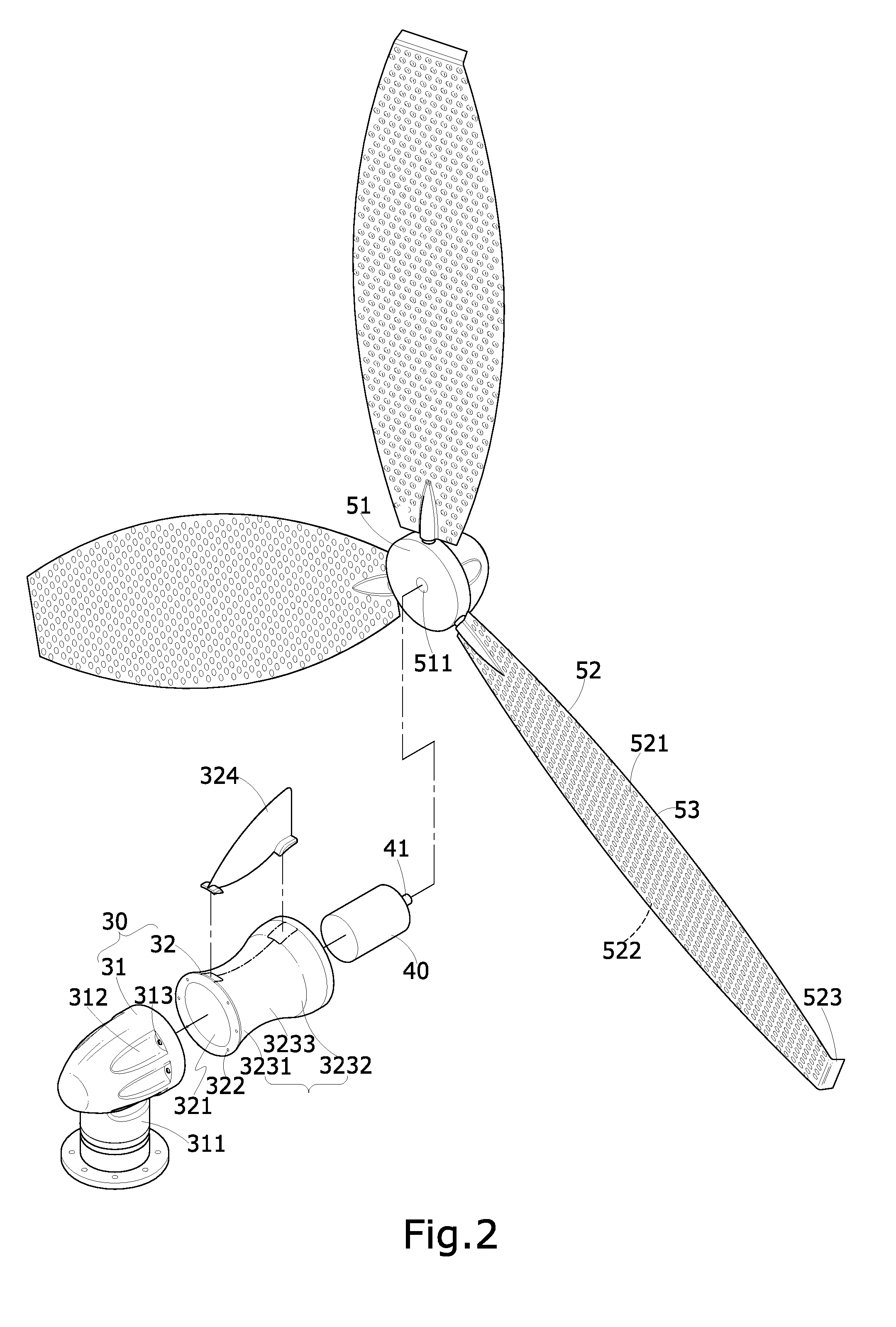
[0009]As such, when the present invention is driven by a high speed airflow, the reducing section of the nacelle body induces a vacuum effect that attracts the airflow and the expanding section changes a rising angle of the airflow to make the airflow directly impinge the blades of the vane wheel, so as to reduce turbulence and increase wind pressure, thereby substantially improving utilization efficiency of wind energy. The fin set in the circumferentially extending curved slot provides a deflecting angle with respect to a flow direction of airflow when winds change directions, so as to induce a driving force for making shift of the nacelle body and thus provide the present invention with a function of automatic wind tracking. Further, when the vane wheel rotates, the down wash formed at an end of each blade may suppress the occurrence of tip vortex and block and guide airflow to reach rearward, thereby substantially improve the utilization efficiency of wind energy in wind generation and reduce the wind noise.

Problems solved by technology

Wind energy is an almost unlimited and easy to use energy source and is generated due to air convection caused by locally unbalanced heating of the atmosphere.
This makes the wind turbine of this type very expensive.

Method used


Image

  • Wind turbine
  • Wind turbine
  • Wind turbine

Examples


Embodiment Construction

[0018]The following descriptions are exemplary embodiments only, and are not intended to limit the scope, applicability or configuration of the invention in any way. Rather, the following description provides a convenient illustration for implementing exemplary embodiments of the invention. Various changes to the described embodiments may be made in the function and arrangement of the elements described without departing from the scope of the invention as set forth in the appended claims.

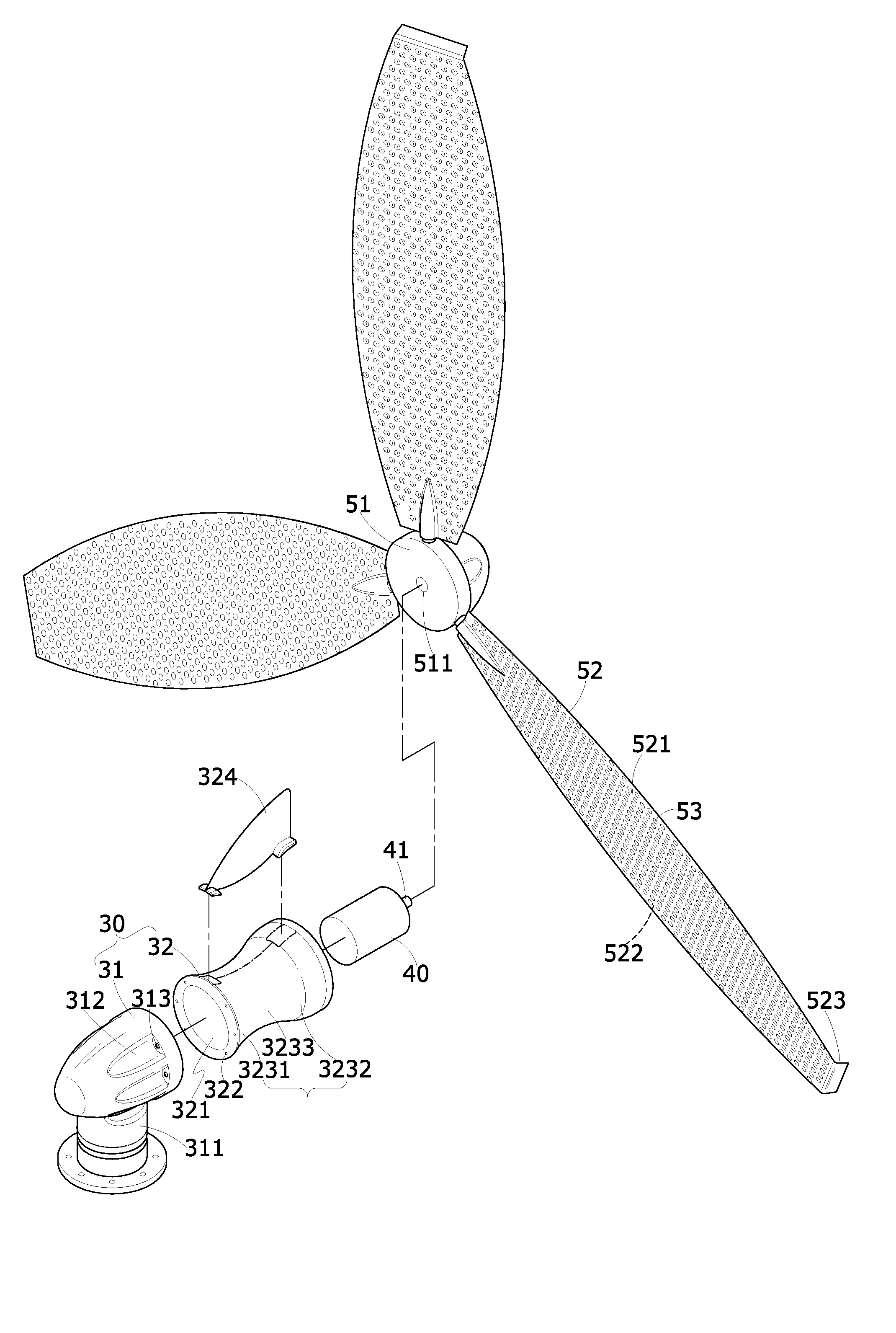
[0019]With reference to FIGS. 2 and 3, a wind turbine constructed in accordance with a preferred embodiment of the present invention comprises the following components:

[0020]A nacelle 30 is composed of a nose 31 and a body 32. The nacelle nose 31 is of a sharp conic shape and is provided with a retention base 311 at an underside thereof. The nacelle nose 31 has a circumferential surface, which defines a plurality of recesses 312 each forming at least one coupling hole 313. The nacelle body 32 is of ...


PUM


Abstract

A wind turbine includes a nacelle that houses a dynamo and a vane wheel coupled to an end of the dynamo. The nacelle is movably mounted to a post. The nacelle has a body forming a circumferentially extending curved slot that has a front portion forming a reducing section and a rear portion forming an expanding section. The vane wheel has a hub at a center thereof and including a plurality of blades radially extending therefrom. Each blade has an end forming a down wash. With the curved design of the nacelle body, the rising angle of airflow exiting the nacelle is improved and with the down wash, the occurrence of tip vortex is suppressed, whereby the utilization efficiency of wind energy in the wind generation operations is improved.

Description

TECHNICAL FIELD OF THE INVENTION[0001]The present invention generally relates to wind generation, and particularly to a wind generation structure comprising a nacelle having a curved configuration and employing down washes to reduce the occurrence of tip vortexes.DESCRIPTION OF THE PRIOR ART[0002]Recently, scientists have been devoted themselves in the development of new and substitute energy sources, among which the most commonly known includes solar energy, wind energy, tidal energy, or biomass energy, for the purposes of converting the unlimited power provided by the Nature into all kinds of useful energy. Wind energy is an almost unlimited and easy to use energy source and is generated due to air convection caused by locally unbalanced heating of the atmosphere. A conventional wind turbine uses the air flows of wind to drive the rotation of a vane wheel, so as to convert the wind energy into electrical energy. Besides the site of installation of the wind turbine, the structure o...

Claims


Application Information

Patent Timeline
Patent Type & Authority Applications(United States)
IPC IPC(8): F03D9/00F03D1/06
CPCF05B2240/13F05B2240/30F05B2240/32Y02E10/726Y02E10/721F03D1/06Y02B10/30F03D1/0675Y02E10/72
Inventor LEE, JIA-YUAN
Owner LEE JIA YUAN
Learn More