Standing wave detection apparatus and method of controlling the same

a technology of standing wave and detection apparatus, which is applied in the direction of reverberation time, instruments, measurement devices, etc., can solve the problems of increasing the load on the user, difficult to detect the frequency of all standing wave generated in the listening area, and requiring long time, so as to achieve efficient detection of standing wave generated

Active Publication Date: 2010-12-02
CANON KK
View PDF7 Cites 92 Cited by
  • Summary
  • Abstract
  • Description
  • Claims
  • Application Information

AI Technical Summary

Benefits of technology

[0011]The present invention provides a technique of eff

Problems solved by technology

The sound of a frequency at which a standing wave is generated becomes too loud and booms at the position of a peak (anti-node), or is conversely hard to listen at the position of a dip (node), resulting in serious problems for human audibility.
However, since a standing wave whose maximum amplitude is determined by its position in the space inevitably has position dependence, it is very difficult to detect the frequencies of all standing waves generated in the listening area based on the fixed-point measurement results at several discrete points. FIG. 19 is a graph showing an example of a result obtained by performing fixed-point measurement at 21 points at an interval of 10 cm on a 2-m direct path in an area assumed to be a listening area in an actual room.
However, the fixed-point measurement at a fine measurement point interval increas

Method used


Image

  • Standing wave detection apparatus and method of controlling the same
  • Standing wave detection apparatus and method of controlling the same
  • Standing wave detection apparatus and method of controlling the same

Examples


first embodiment

[0038]A standing wave detection apparatus according to the first embodiment of the present invention will be described below by exemplifying a standing wave detection apparatus for performing measurement while moving in a predetermined space.

[0039]Measurement (to be referred to as “mobile measurement” hereinafter) while moving in a predetermined space such as a room is a method of performing measurement continuously at positions while moving a microphone without stopping at each measurement point. FIG. 20 is a graph showing examples of sound pressure level (200-Hz component) measurement results in fixed-point measurement and mobile measurement. Reference numeral 2000a indicates a fixed-point measurement result; and 2000b and 2000c, mobile measurement results. Note that since the results 2000b and 2000c are obtained by measurement while moving, the abscissa represents both the position and the measurement time. Comparing the results 2000a and 2000b reveals that the dip near the cente...

second embodiment

[0070]In the second embodiment, a standing wave detection apparatus having a level adjuster different from that of the first embodiment will be described. Note that the remaining components and operations are the same as in the first embodiment, and a description thereof will not be repeated.

[0071]

[0072]FIG. 6 is a block diagram showing a level adjuster 600 according to the second embodiment. Unlike the first embodiment, the level adjuster 600 includes a maximum adjustment amount determiner 601 as a processing block.

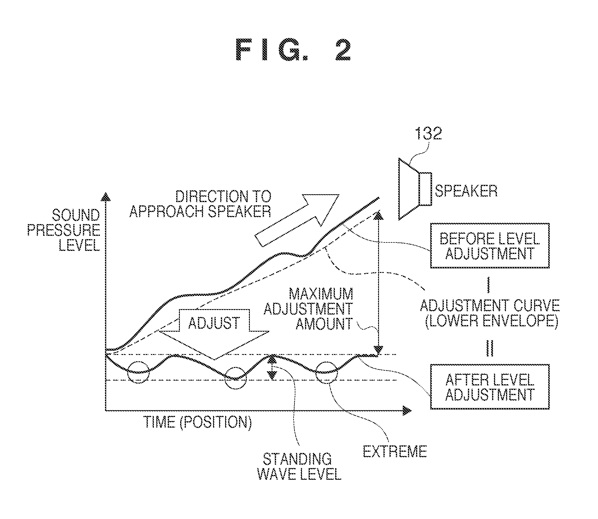
[0073]As described in the first embodiment, a level adjuster 123 removes a variation in the level caused by the distance between a speaker 132 and a microphone 105 from sound pressure level data. If the adjustment amount at that time is too large, it indicates that the measurement position of the microphone 105 is too close to the speaker 132. At this time, since the direct sound from the speaker 132 is superior to the reflected sound from the walls, the peaks and dips o...

third embodiment

[0077]In the third embodiment, a standing wave detection apparatus having a standing wave detector different from that of the first embodiment will be described. Note that the remaining components and operations are the same as in the first embodiment, and a description thereof will not be repeated.

[0078]

[0079]FIG. 8 is a block diagram showing a standing wave detector 800 according to the third embodiment. Unlike the first embodiment, the standing wave detector 800 includes an extreme interval determiner 801 as a processing block.

[0080]As described in the first embodiment, a standing wave detector 124 detects the variation range (standing wave level) and extrema of sound pressure level data adjusted by a level adjuster 123, thereby detecting standing waves. An extreme is a local minimum or local maximum which preferably appears every half wavelength of a wavelength determined by the frequency of a standing wave, i.e., the extrema preferably have a predetermined interval.

[0081]Howeve...


PUM


Abstract

To efficiently detect a standing wave generated in a room, a standing-wave detection apparatus for detecting a standing wave in a predetermined space, comprises: a sound-receiving unit adapted to receive a sound generated from a sound source arranged in the predetermined space; a storage unit adapted to store time series sound pressure level data acquired by the sound-receiving unit during movement along a path in the predetermined space; an adjustment unit adapted to adjust the time series sound pressure level data stored in the storage unit, based on an adjustment curve determined using a lower envelope of the time series sound pressure level data stored in the storage unit; and a detection unit adapted to detect an existence position of a standing wave in the predetermined space based on the adjusted time series sound pressure level data.

Description

BACKGROUND OF THE INVENTION[0001]1. Field of the Invention[0002]The present invention relates to a technique of detecting a standing wave in a room.[0003]2. Description of the Related Art[0004]When a sound source such as a speaker generates a sound in a room of, e.g., a home, not only direct sounds that reach various points of the room at minimum distances but also reflected sounds from various planes such as the walls, ceiling, and floor of the room are generated. These sound waves overlap each other. If a composite wave formed by the overlapping waves moves neither forward nor backward, and the maximum amplitude of the composite wave at each point is determined not by time but only by its position in the space, the composite wave is called a standing wave.[0005]Especially, the standing wave is readily generated between planes opposing each other at a frequency at which the distance between the planes is an integer multiple of the half wavelength of the sound wave. At this time, th...

Claims


Application Information

Patent Timeline
IPC IPC(8): H04R29/00
CPCG01H7/00H04S7/305
Inventor TAWADA, NORIAKI
Owner CANON KK
Why Eureka
Try Eureka