Probe Microscope

a technology of probe microscope and probe, which is applied in the field of probe microscope, can solve the problems of insufficient width of potential window to detect metallic ions of different varieties, inability to perform correct quantitative analysis of ions near the surface of samples, and difficulty in defining metallic ions of detection objects

Inactive Publication Date: 2010-12-02
HITACHI LTD
View PDF14 Cites 14 Cited by
  • Summary
  • Abstract
  • Description
  • Claims
  • Application Information

AI Technical Summary

Benefits of technology

[0007]In view of the problem of the conventional art, an object of the present invention is to provide a probe microscope that permits qualitative and quantitative evaluation on ions existing near the surface of a sample and permits to detect further simply and easily such as impurities, flaws and corrosion origins existing on the sample in high sensitivity.

Problems solved by technology

However, when connecting the sample to the electrochemical device and causing the sample itself to react, there arises a problem that qualitative and quantitative analysis on ions existing near the surface of the sample cannot be performed correctly.
More specifically, when probe potential is scanned toward the side of negative potential beyond from a predetermined potential, protons in the solution are reduced to generate hydrogen, and since a reducing current due to such hydrogen is detected at the same time, it becomes sometimes difficult to specify the metallic ions of detection object.
When platinum is used, since a potential window (a region where the current is substantially zero) is narrow and is about 0.3V, the width of the potential window cannot be said sufficient for detecting varieties of metallic ions.

Method used


Image

  • Probe Microscope
  • Probe Microscope
  • Probe Microscope

Examples


embodiment 1

An Example when AFM is Applied

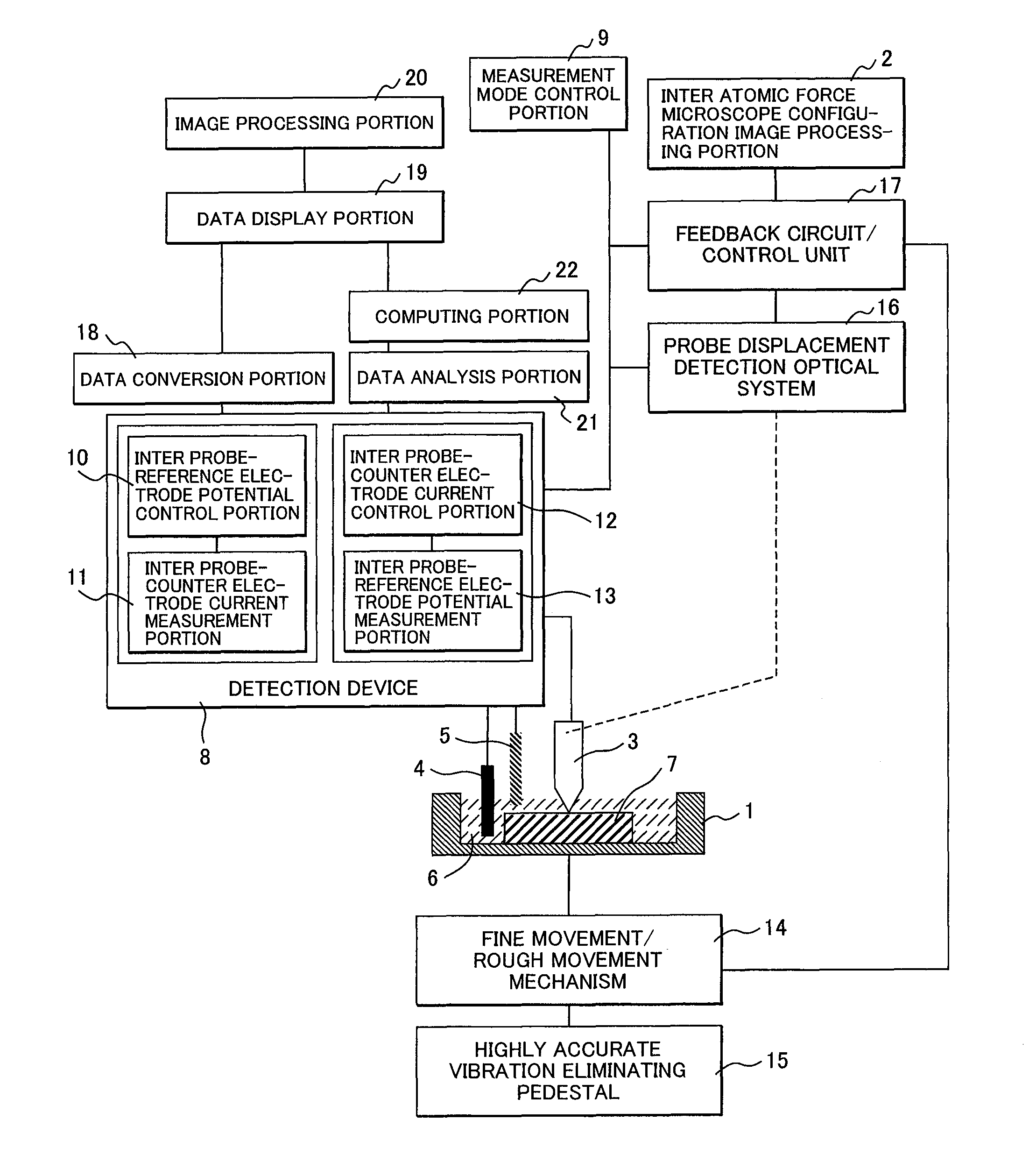
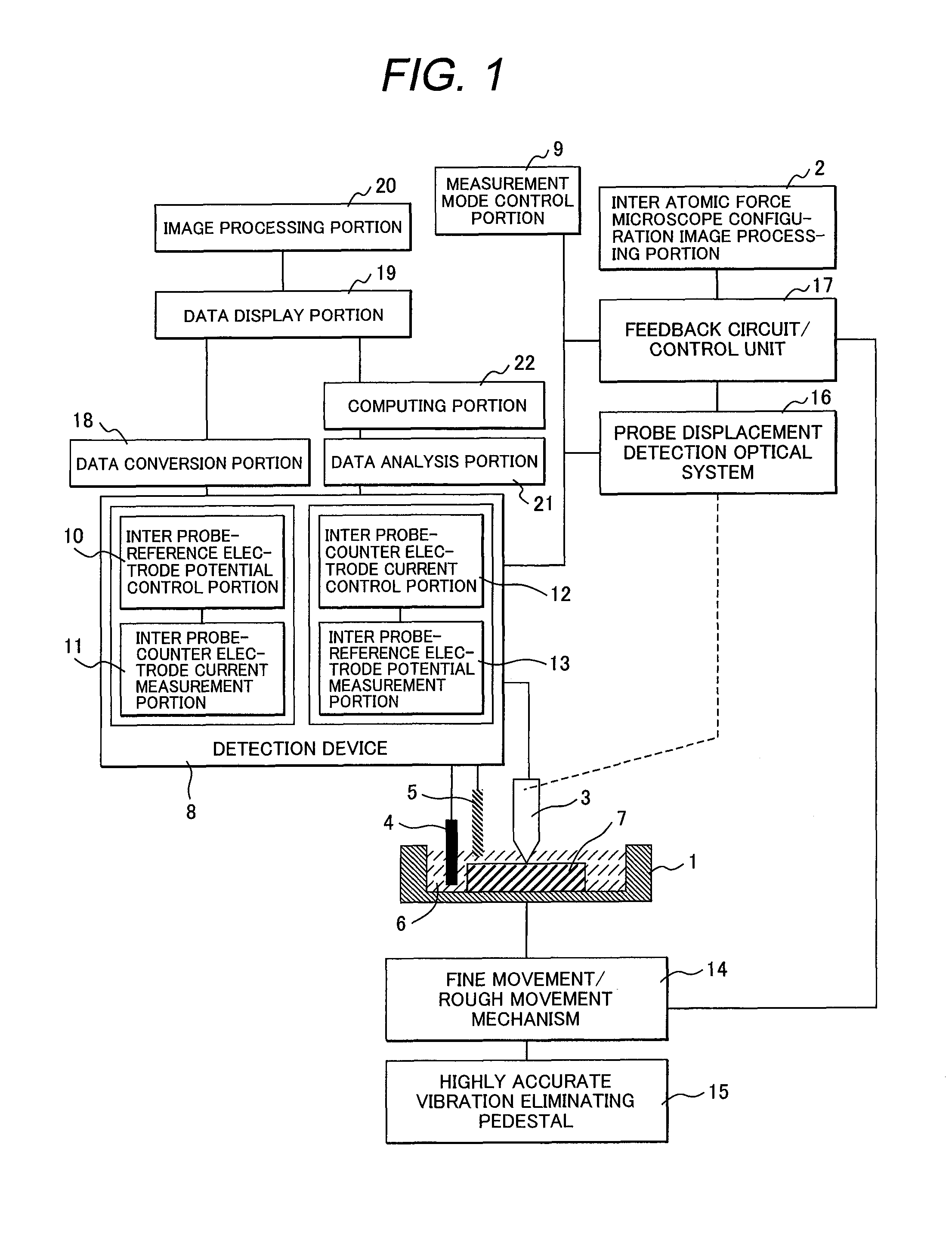
[0024]In the present embodiment, an example of a probe microscope will be explained in which a sample is observed by making use of primarily a mechanism of an atomic force microscope (AFM). FIG. 1 is a schematic constitutional diagram of a probe microscope according to the present embodiment.

[0025]A device of the present embodiment includes a test cell 1 and a moving mechanism 14 for moving the position of the test cell 1, and a probe 3, a counter electrode 4 and a reference electrode 5 are provided so as to position respectively within the test cell 1. The moving mechanism 14 can effect both rough movement that varies greatly the position of the test cell 1 and fine movement for performing fine adjustment thereof. The probe 3, the counter electrode 4 and the reference electrode 5 are disposed in such a manner that when liquid 6 is poured in the test cell 1, the same are immersed under the liquid 6.

[0026]A sample 7 representing an inspection object such...

embodiment 2

An Example when STM is Applied

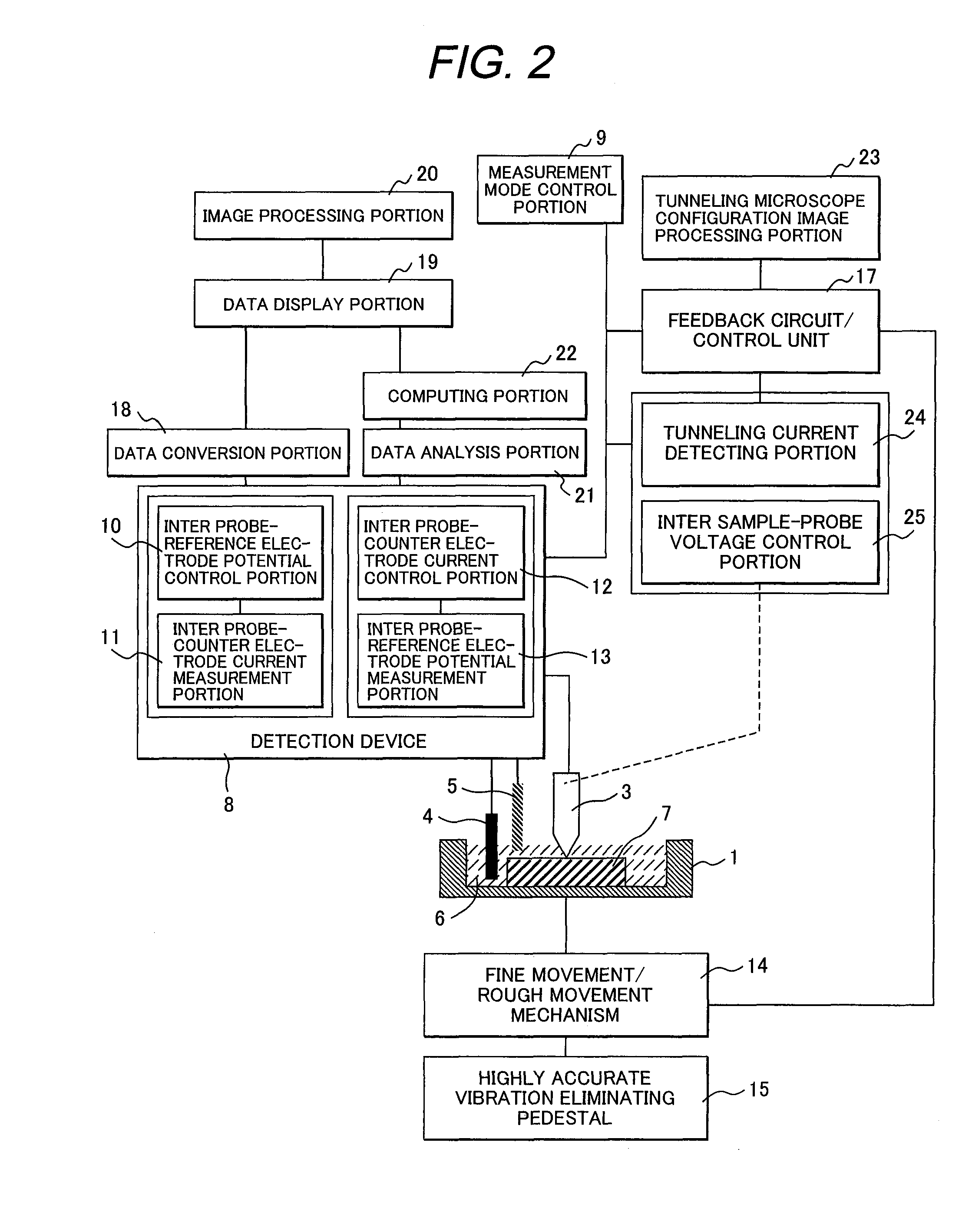
[0064]In the present embodiment, another example of a probe microscope will be explained in which a sample is observed by making use of primarily a mechanism of a scanning tunneling microscope (STM). FIG. 2 is a schematic constitutional diagram of a probe microscope according to the present embodiment.

[0065]A different point of the present embodiment from embodiment 1 is that in place of the probe displacement detection optical system 16 a tunneling current detection portion 24 and an inter sample-probe voltage control portion 25 are provided.

[0066]In the configuration measurement mode with the present probe microscope, through moving the test cell 1 with the fine movement / rough movement mechanism 14, the probe 3 and the sample 7 are approximated each other. According to the principle of the scanning tunneling microscope the probe 3 is approximated to the sample 7, with the inter sample-probe voltage control portion 25 a voltage is applied between the s...


PUM


Abstract

An object of the present invention is to provide a probe microscope that permits qualitative and quantitative evaluation on ions existing near the surface of a sample and permits to detect further simply and easily such as impurities, flaws and corrosion origins existing on the sample in high sensitivity. A probe microscope according to the present invention is provided with a test cell that holds a sample and permits to receive liquid, a probe, a counter electrode, a reference electrode, a drive mechanism that causes the probe to follow the surface of the sample as well as to scan the same, a potential control portion that controls a potential between the probe and the reference electrode and a current measuring portion that measures a current flowing between the probe and the counter electrode, and is characterized in that the material of the probe is constituted by a conductive body containing any of gold or gold alloy, carbon or carbon compound, boron, zinc, lead, tin and mercury.

Description

CLAIM OF PRIORITY[0001]The present application claims priority from Japanese application serial no. 2009-129791, filed on May 29, 2009, the content of which is hereby incorporated by reference into this application.FIELD OF THE INVENTION[0002]The present invention relates to a probe microscope that detects metal ions existing in liquid through controlling electrical potential of a probe and evaluates qualitatively and quantitatively a substance deposited.DESCRIPTION OF PRIOR ART[0003]In these days, in order to enhance reliability of electronic and electrical appliances, technology of evaluating corrosion and estimating the corrosion is necessitated. Although objective corrosions of metallic materials are diversified, in particular, in a field of information appliances using many electronic parts, it is indicated that corrosion of micro scale affects the reliability of the appliances in association with their high integration and miniaturization. For this reason, technology using too...

Claims


Application Information

Patent Timeline
Patent Type & Authority Applications(United States)
IPC IPC(8): G01Q30/00
CPCB82Y35/00G01Q60/02G01Q60/44
Inventor HARADA, MOTOKOHONBO, KYOKOMABUCHI, KATSUMI
Owner HITACHI LTD
Why Eureka
Try Eureka