Sensor array

Inactive Publication Date: 2010-12-09
MOOG INSENSYS
View PDF9 Cites 2 Cited by
  • Summary
  • Abstract
  • Description
  • Claims
  • Application Information

AI Technical Summary

Benefits of technology

[0009]In embodiments of the invention, the width of the sensor support panel is greater than 5 times, preferably greater than 10 times, more preferably greater than 25 times and possibly greater than 40 times the width of the connecting member. In determining this ratio, the average width of the sensor support panel or connecting member calculated along its entire extent in the longitudinal direction should be used. The significantly greater width of the sensor support panels provides sufficient space for the optical fibre to form the curve without kinking and also provides room for variation in the transverse extent of the curve. Varying the transverse extent of the curve when the optical fibre is applied to the sensor support panel allows any slack in the optical fibre between support panels to be taken up by extending the curve.
[0010]The length of the connecting members may be greater tha

Problems solved by technology

On the one hand, optical fibres are delicate components that require very accurate align

Method used


Image

  • Sensor array
  • Sensor array
  • Sensor array

Examples


Embodiment Construction

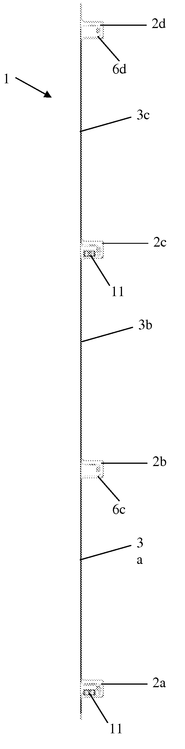
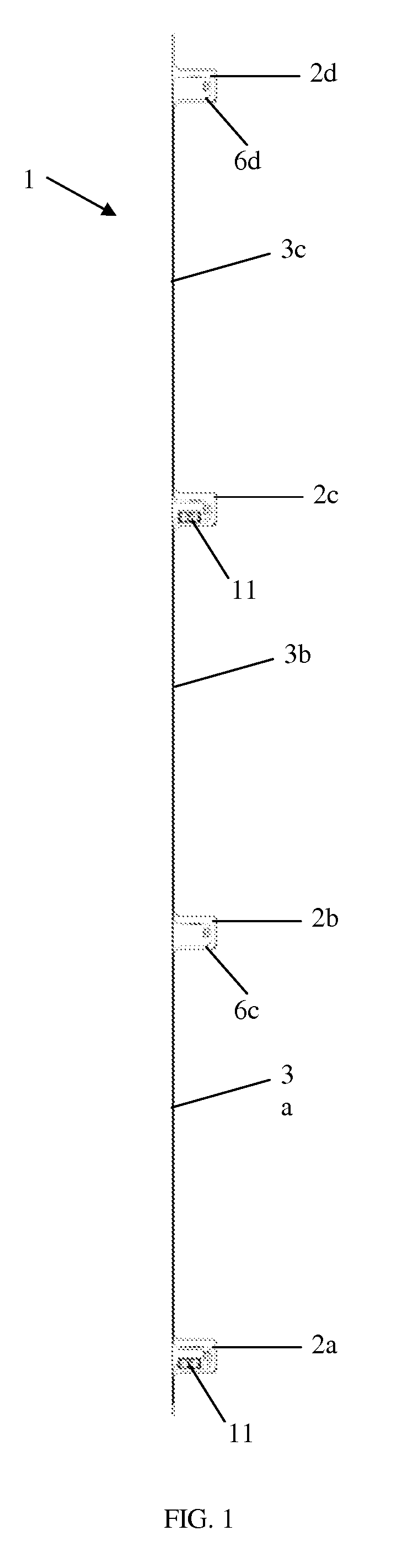
[0024]FIG. 1 shows an optical fibre strain sensor array 1 according to an embodiment of the invention. The array comprises four sensor support panels 2a-2d connected by three connecting members 3a-3c. A 250 micron unsleeved optical fibre 4 runs from a terminal portion 5 of the array to the first sensor support panel 2a, where it forms a first curve (or loop) 6a on the first sensor support panel 2a. The optical fibre 4 continues from the first sensor support panel 2a along the first connecting member 3a to the second sensor support panel 2b, where the optical fibre 4 forms a second curve 6b on the second sensor support panel 2b. Similarly, the optical fibre 4 continues from the second sensor support panel 2b along the second connecting member 3b to the third sensor support panel 2c, where the optical fibre 4 forms a third curve 6c on the third sensor support panel 2c. Finally, the optical fibre 4 continues from the third sensor support panel 2c along the third connecting member 3c to...


PUM


Abstract

An optical fibre strain sensor array comprises several sensor support panels spaced in its longitudinal direction and at least one connecting member extending in the longitudinal direction, which mechanically interconnects the sensor support panels. An optical fibre is supported by the sensor support panels and the connecting member. The optical fibre extends with the connecting member between the sensor support panels and forms a curve on the sensor support panel, the curve including at least one portion of the optical fibre that extends in the transverse direction. The width of the connecting member is substantially less than the width of the sensor support panels, such that the connecting member is capable of flexure in the transverse direction. This has the advantage that the connecting member can be flexed to take up any slack during installation of the optical fibre strain sensor array in a wind turbine blade and can be fitted to the turbine blade even if the blade has a conical shape.

Description

FIELD OF THE INVENTION [0001]This invention relates to a sensor array for structural monitoring, in particular the structural monitoring of wind turbine blades and, in particular, to the structural monitoring of wind turbine blades using fibre optic strain sensors.BACKGROUND TO THE INVENTION [0002]Blades for wind turbines are typically constructed of glass-reinforced plastics (GRP) on a sub-structure, which may be formed of wood, glass fibre, carbon fibre, foam or other materials. Graphite fibre in epoxy resin is also used. The plastics resin can be injected into a mould containing the sub-structure to form the outer surface of the blade. The blade may also be built up as a series of layers of fibre material and resin. In some cases, the fibre material is pre-impregnated with resin.[0003]A typical wind turbine blade may have a length of between 20 and 60 metres or more. As the interior of the blade is generally hollow, a “floor” is provided within the blade proximate the hub-engagin...

Claims


Application Information

Patent Timeline
IPC IPC(8): G01L1/24
CPCG01L1/246G01D5/35316G01M11/085G01D5/35383
Inventor VOLANTHEN, MARKANGUS, ROBERT ALLAN
Owner MOOG INSENSYS
Why Eureka
Try Eureka