
Hand-held power tool, particularly a drilling and/or chisel hammer, having a damper unit

a technology of damper unit and power tool, which is applied in the direction of portable power tools, power driven tools, percussive tools, etc., can solve the problems of rotatory vibration, drawing energy from oscillation, and user discomfort of power tools, so as to reduce oscillation, reduce oscillation, and achieve compact design of the vibration absorber unit

Inactive Publication Date: 2010-12-09
ROBERT BOSCH GMBH
View PDF9 Cites 19 Cited by
  • Summary
  • Abstract
  • Description
  • Claims
  • Application Information

AI Technical Summary

Benefits of technology

[0006]Advantageous modifications and improvements of the defining characteristics disclosed in the main claim are possible by means of the measures taken in the dependent claims.
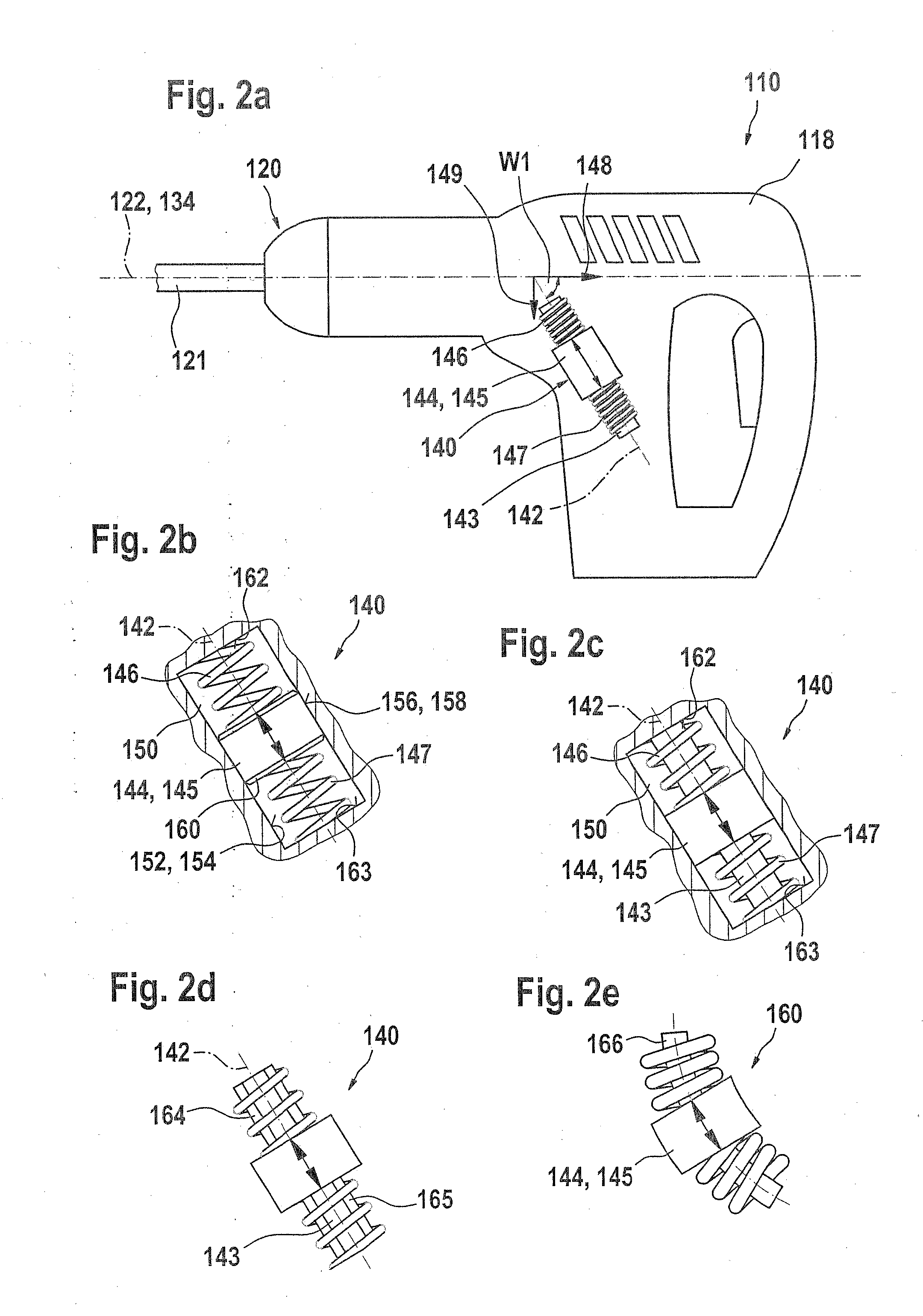
[0008]A particularly simple embodiment of a vibration absorber unit according to the invention is achieved in that a degree of freedom of the mobile vibration absorbing element is embodied as a transverse movement. In this case, it must be viewed as an additional advantage that the vibration absorbing element of the vibration absorber unit according to the invention has two orthogonal movement components, the one movement component extending parallel to the line of action and the other movement component extending orthogonal to the main oscillation axis. In this way, parallel and orthogonal oscillation modes can be damped with a single vibration absorber unit.

Problems solved by technology

Users of the power tool find these vibrations unpleasant.
The return springs in turn damp the displacements of the vibration absorbing element, thus drawing energy from the oscillations.
In particular, rotatory vibrations occur due to the recoiling of a tool that is driven at least in rotary fashion during the machining of a work piece.
In addition, in hand-held power tools in which the center of mass is situated far away from a tool axis axis, tilting moments occur, which excite vibrations transverse to the impact direction.

Method used


Image

  • Hand-held power tool, particularly a drilling and/or chisel hammer, having a damper unit
  • Hand-held power tool, particularly a drilling and/or chisel hammer, having a damper unit
  • Hand-held power tool, particularly a drilling and/or chisel hammer, having a damper unit

Examples


Embodiment Construction

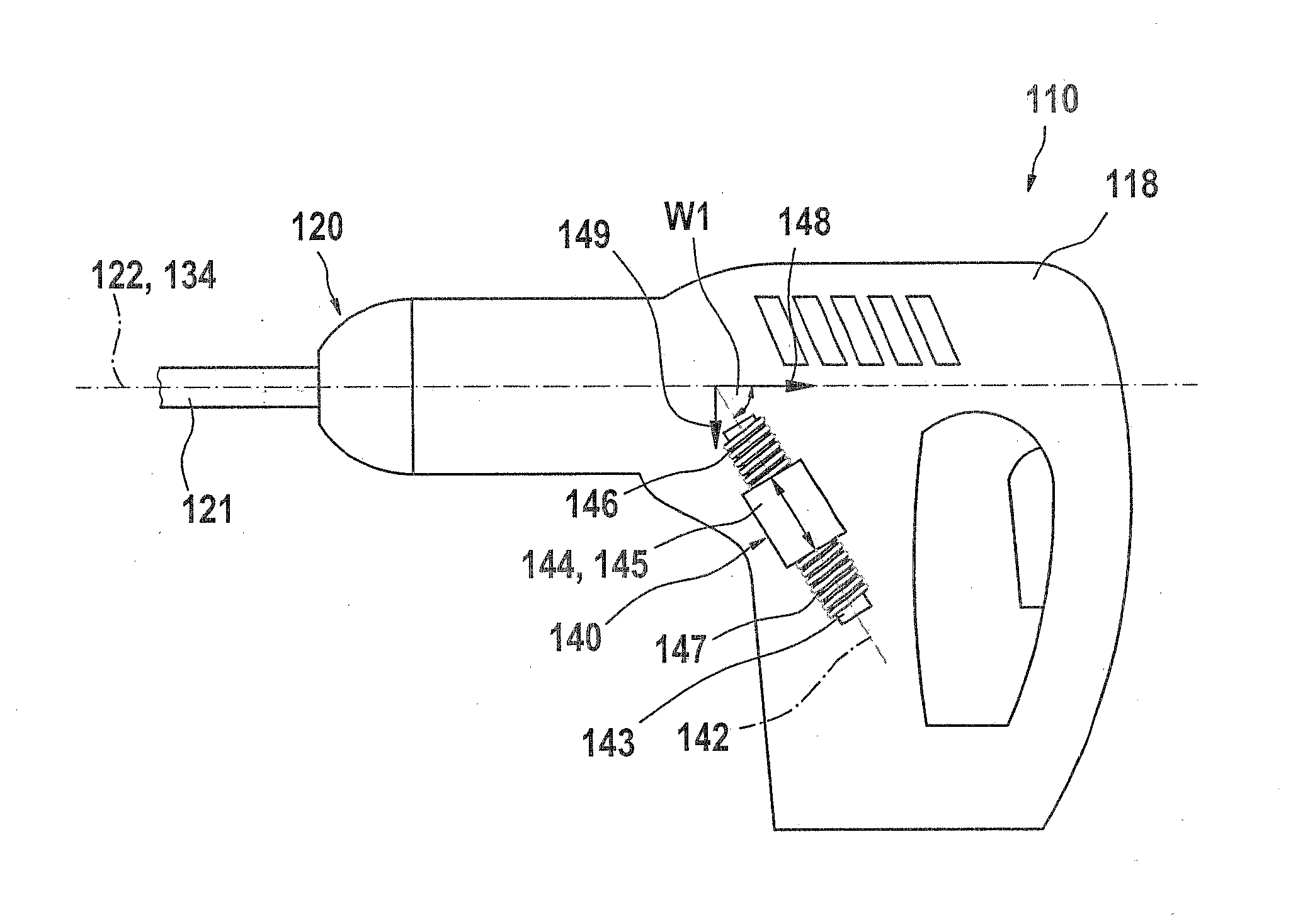
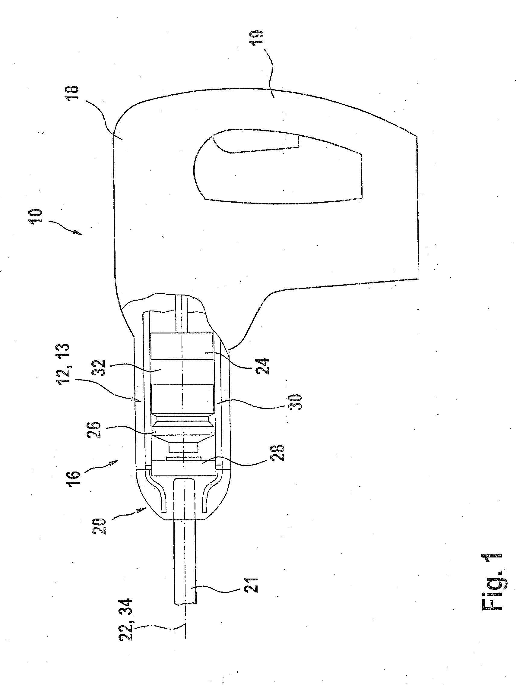
[0041]FIG. 1 is a schematic depiction of a rotary hammer 10 of the kind known from the prior art, as an example of a hand-held power tool. The rotary hammer includes an impact mechanism 12, which in this case is embodied in the form of an air-cushion impact mechanism 13, for example, and a drive unit 14 that is not shown in detail. The air-cushion impact mechanism 13 is situated in a frontal housing region 16 of a machine housing 18. The machine housing 18 is also connected to at least one handle 19. A tool holder 20 is situated at the end surface of the frontal housing region 16. An insert tool 21 can be inserted into it. A variety of tool holders 20 are known from the literature and need not be discussed in detail here. The insert tool 21, in its longitudinal span, defines a machine axis 22. The air-cushion impact mechanism 13 is situated coaxially around this machine axis 22.

[0042]The air-cushion impact mechanism 13 in the present example includes an axially movable piston 24, an...


PUM


Abstract

A hand-held power tool, in particular an impact driver, an impact drill, or a rotary hammer, is proposed, which has a drive unit and / or output with at least one line of action, which produces at least oscillations along the line of action. In order to reduce these oscillations, the hand-held power tool is equipped with at least one vibration absorber unit. The vibration absorber unit has at least one mobile vibration absorbing element, which has at least one degree of freedom of movement. This degree of freedom of movement encloses at least one angle not equal to zero with the line of action.

Description

PRIOR ART[0001]The invention relates to a hand-held power tool, in particular an impact driver, an impact drill, or a rotary hammer, having at least one drive unit and / or output. The drive unit and / or output has at least one line of action, which is defined in a rotary hammer, for example, by the axial action direction of an impact mechanism. At least along this line of action, the drive unit and / or output produces oscillations, which can be transmitted in the form of vibrations to a housing and / or handle of the power tool. Users of the power tool find these vibrations unpleasant. In order to reduce these oscillations / vibrations, the power tool is equipped with at least one vibration absorber unit.[0002]A variety of hand-held power tools with vibration absorber units for reducing oscillation are already known. Among others, EP 1 252 976 A1 has disclosed a vibration absorber unit, which, when used in hand-held power tools operated in a hammering mode such as rotary and / or chisel hamm...

Claims


Application Information

Patent Timeline
IPC IPC(8): B25D17/24
CPCB25D17/24B25D2217/0092B25D2217/0084B25B21/02B25F5/006
Inventor BAUMANN, OTTOSCHMID, HARDY
Owner ROBERT BOSCH GMBH
Learn More